Keysight B1505A Configuration and Connection Guide 5-31
Connection Guide for Wafer Prober and Your Own Test Fixture
To Connect Module Selector
NOTE Controlling N1258A input-to-output path
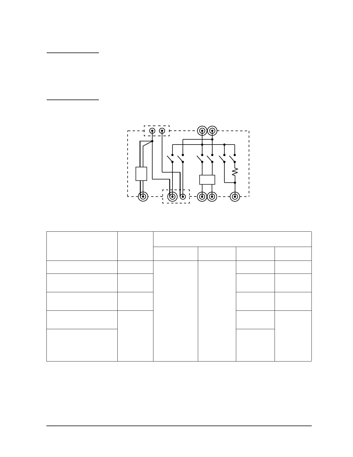
The configuration and the default I/O path of the N1258A are set by using the Module
Selector tab screen of the Configuration window of the EasyEXPERT software. The
connection path from the input port to the output port is controlled by each test setup. And
the N1258A switching status is indicated by the Status indicator mounted on the front
panel. See Figure 5-14 and Table 5-22 for the indication and the connection path.
Figure 5-14 Module Selector Simplified Internal Connections
Table 5-22 Module Selector Status Indicator and Input-to-Output Connection Path
Measurement resource
used for the test
Status
indicator
Input-to-output connection
1
of output terminals
1. In the normal state, the N1258A makes the path to the output port from the input port specified by the
Default field. When a measurement is performed, the N1258A performs automatic switching in every
test. The N1258A makes the path to the output port from the measurement resource used for the test.
Low Sense Low Force High Sense High Force
2
2. This condition is when all Input fields HVSMU, HCSMU, and HPSMU are blank.
Open HCSMU Low
Sense
+ GNDU Force
+ GNDU Sense
HCSMU
Low Force
Open Open
HPSMU or MPSMU HPSMU HPSMU
Sense
HPSMU
Force
HCSMU or DHCSMU HCSMU HCSMU
High Sense
HCSMU
High Force
HVSMU or HVMCU HVSMU HVSMU
Force Open
HVSMU/HVMCU and
built-in series resistor
HVSMU
Force
+Series
resistor
Low High
SF
S: Sense
F: Force
P.A
P.A
GNDU HCSMU HPSMU HVSMU
SF
SF
SF
F
P.A:
Protection adapter
SF
GNDU force and sense
are connected to Low
sense line.
HVSMU force is connected
to High sense line.
100 kW

 Loading...


