5-30 Keysight B1505A Configuration and Connection Guide
Connection Guide for Wafer Prober and Your Own Test Fixture
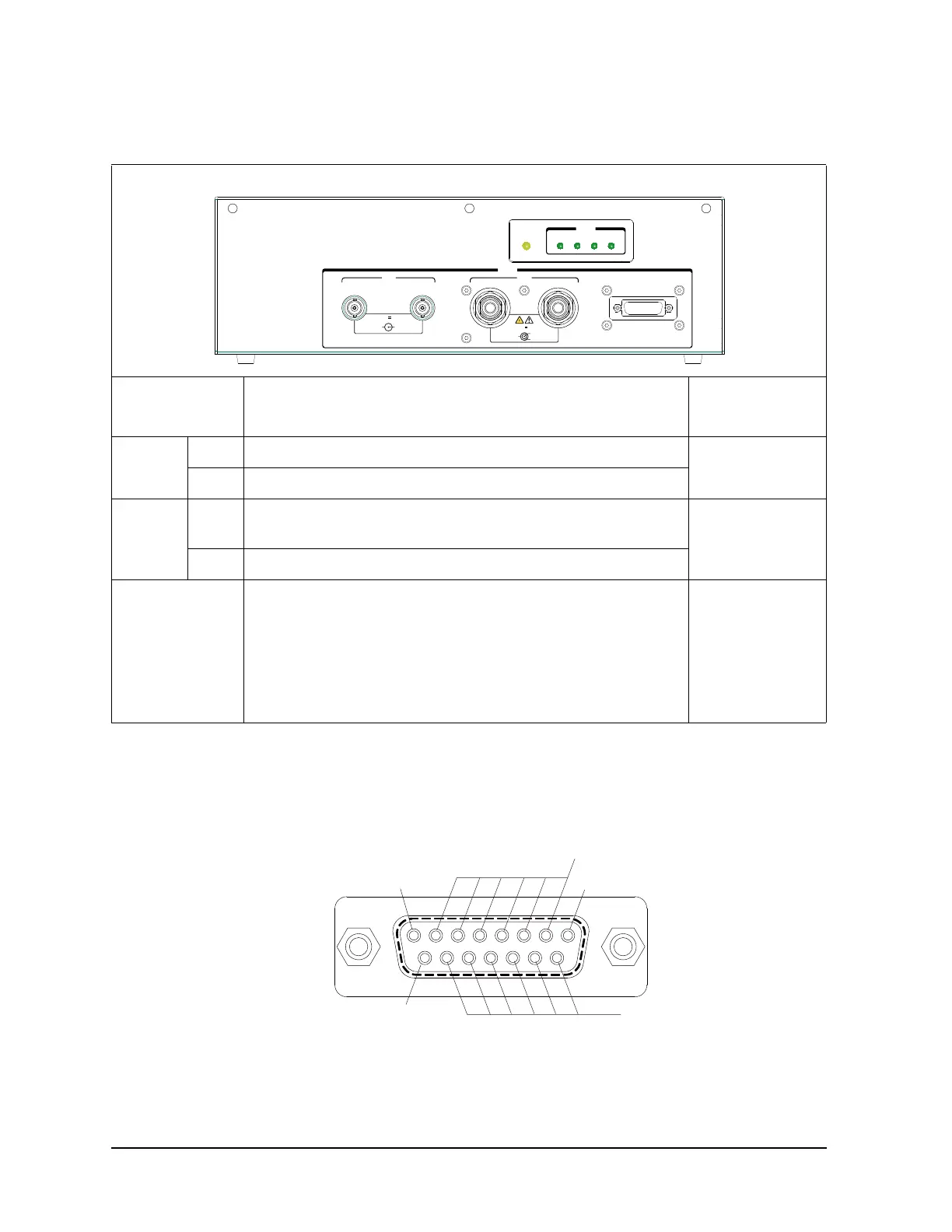
To Connect Module Selector
Table 5-21 To Connect N1258A Output
Figure 5-13 External Relay Control Output Connector
N1258A
terminals
1
1. The connectors are compatible with the 16493S-020 adapter output connectors.
Required cables/Description Connect to
Low Force Coaxial cable with BNC(m) connector. N1254A-503 can be used. DUT low terminal
(ex: source)
2
2. Non-Kelvin connection is not allowed. GNDU Force and Sense are internally connected to Low Sense.
See Table 5-22 on page 5-31.
Sense Coaxial cable with BNC(m) connector. N1254A-503 can be used.
High Force Coaxial cable with HV(plug) connector. N1254A-506 can be used.
Use coaxial cable to minimize affect of inductance.
DUT high terminal
(ex: drain)
2
Sense Triaxial cable with HV(plug) connector. N1254A-505 can be used.
External Relay
Control Output
Cable with D-sub 15 pin connector.
See Figure 5-13 for pin assignment. Relay control 1 to 6 are used to
control an external relay and controlled by using the Keysight FLEX
command. See Programming Guide for the FLEX command.
Relay control signal level: 0 V or 12 V, normally 0 V (circuit
common)
Input connector of
your own switch
box like a module
selector
N1258A
Module Selector
Force External Relay
Control Output
Sense
Force
Sense
Output
±3 kV Max
Sense/Force
Guard
Circuit
Common
Power
HPSMU
Open
HCSMU HVSMU
Status
81
15
9
Sense/Force
±42V Max
HighLow
HCSMU
Circuit
Common
12 V
Circut common (0 V)
Circut common (0 V)
Circut common (0 V)
Relay control
1
6
5
4
3
2

 Loading...


