7-52 Keysight B1505A Configuration and Connection Guide
Connection and Ordering Examples
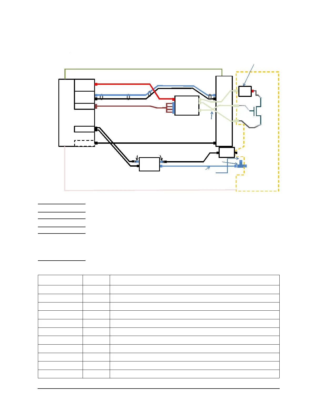
Configuration Examples for Vertical Device Measurement with Wafer Prober
Figure 7-27 Connection example for CV measurement
NOTE The connection diagram n Figure 7-27shows Cds measurement.
NOTE Prober vendor is responsible for cabling inside the shielding box.
NOTE In the connection diagram in Figure 7-27, a High Voltage Triaxial jack connector is used to
connect the wafer chuck. Then you need a adapter to connect the High Voltage Triaxial
plug connector to the SHV connector. Assemble it by using the N1262A-021 or consult
your prober vendor.
Table 7-25 Ordering example
Model/Option Quantity Description
B1505A 1 Power Device Analyzer/Curve Tracer mainframe
B1512A-FG 1 High Current Source Monitor Unit, 20 A/20 V(Pulsed); 1 A/40 V(DC)
B1513C-FG 1 High Voltage Source Monitor Unit, 3000 V/4 mA (Pulsed & DC)
B1514A-FG 1 Medium Current Source Monitor Unit, 1 A/30 V(Pulsed), 100 mA/30 V(DC)
B1520A-FG 1 Multi Frequency Capacitance Measurement Unit Module
16493U 1 High Current BNC Coaxial Cable
16493U-001 2 High Current BNC Coaxial Cable (1.5 m)
16494A 1 Triaxial Cable
16494A-003 1 Triaxial Cable (80 cm)
1250-2405 1 BNC-T Plug (m)-BNC (f)-BNC (f) adapter, 1ea
N1258A 1 Module Selector for B1505A
HVSMU
HCSMU
GNDU
MCSMU
B1505A
16493L (Included in B1505A )
N1258A
D (Chuck)
G
S
HCSMU Non-
Kelvin adapter
1649 3S-0 11
HF
LF
For Gat e
For Drain
For Drain
16493G-001 Digital I/O cable (Included in N1258A)
N1254A-104 TRX(J) to BNC(P) adapter
F
S
F
S
HCS MU F
GNDU
16493J Interlock cable (Included in B1505A)
N1260A
Bi as-T
AC-H
AC-L
AC-Guard
Hc
Hp
Lc
Lp
MFCMU
N1262A-021 can be used for
custom adapter (SHV jack to
HVTRX jack)
HCS MU S
N1300A (Included in MFCMU)
N1254A-518
16494A (Included in the MCSMU)
16494A-003
16493U-001
1250-2405
16493T (Included in the HVSMU. Please change connecƟon manually)
16493S (Included in the HCSMU)
R-Box
1kohm
N1262A-010
Universal
R-Box
N1 26 2A- 0 21

 Loading...


