1.
Fit the timing system crankcase C with the screws R
observing the indicated clamping sequence (tightening
torque at 25 Nm ).
1.
Assemble sensor S by means of capscrew T on carter
C inserting gasket U (tightening torque at 10 Nm ST_06
).
6.7.7 Crankshaft and target wheel pulley assembly
1.
Leave the tool ST_34 mounted ( Fig. 6.44 ) .
2.
Check that the pin A is mounted properly on the
crankshaft Z .
3.
Position the pulley unit W on the crankshaft Z
respecting the reference with the pin A .
4.
Apply Molyslip grease on the screw thread Y .
5.
Clamp the pulley unit W with the screw Y (tightening
torque at 360 Nm ).
6.
Remove the special tool ST_34 ( Fig. 6.44 ) .
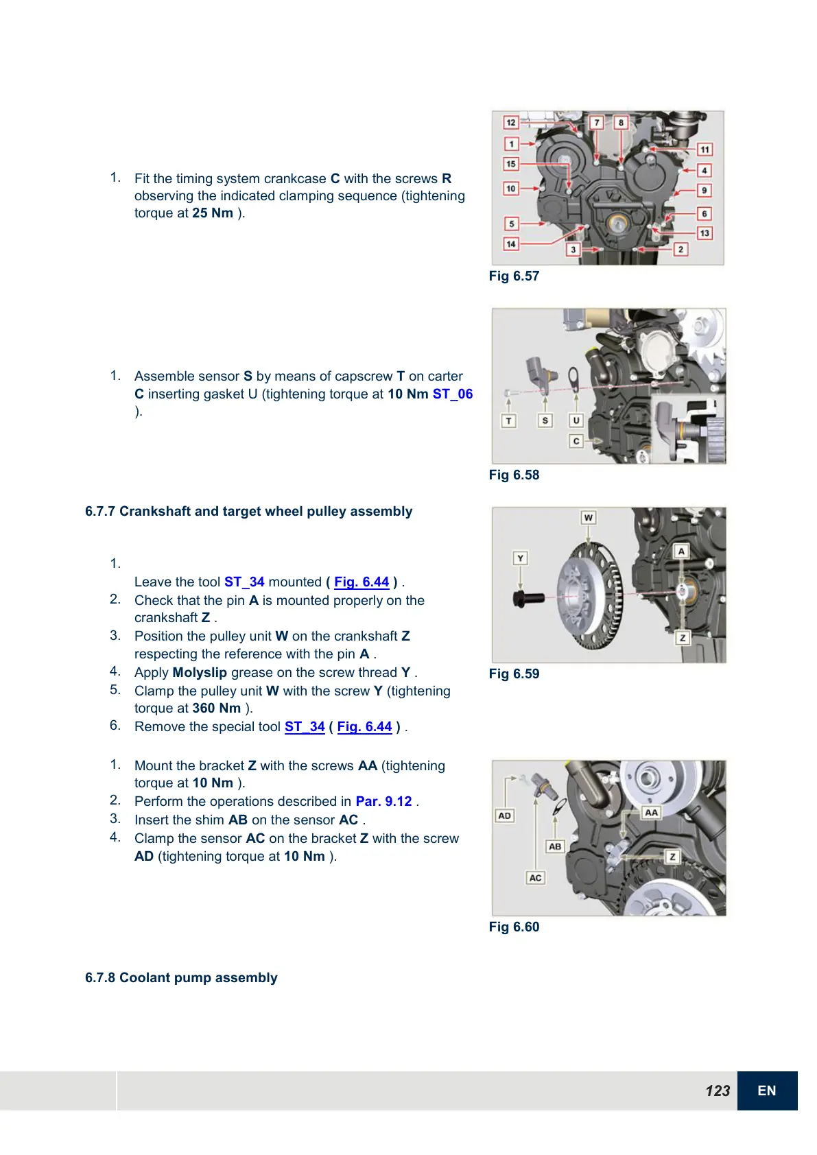
1.
Mount the bracket Z with the screws AA (tightening
torque at 10 Nm ).
2.
Perform the operations described in Par. 9.12 .
3.
Insert the shim AB on the sensor AC .
4.
Clamp the sensor AC on the bracket Z with the screw
AD (tightening torque at 10 Nm ).
6.7.8 Coolant pump assembly

 Loading...


