1.
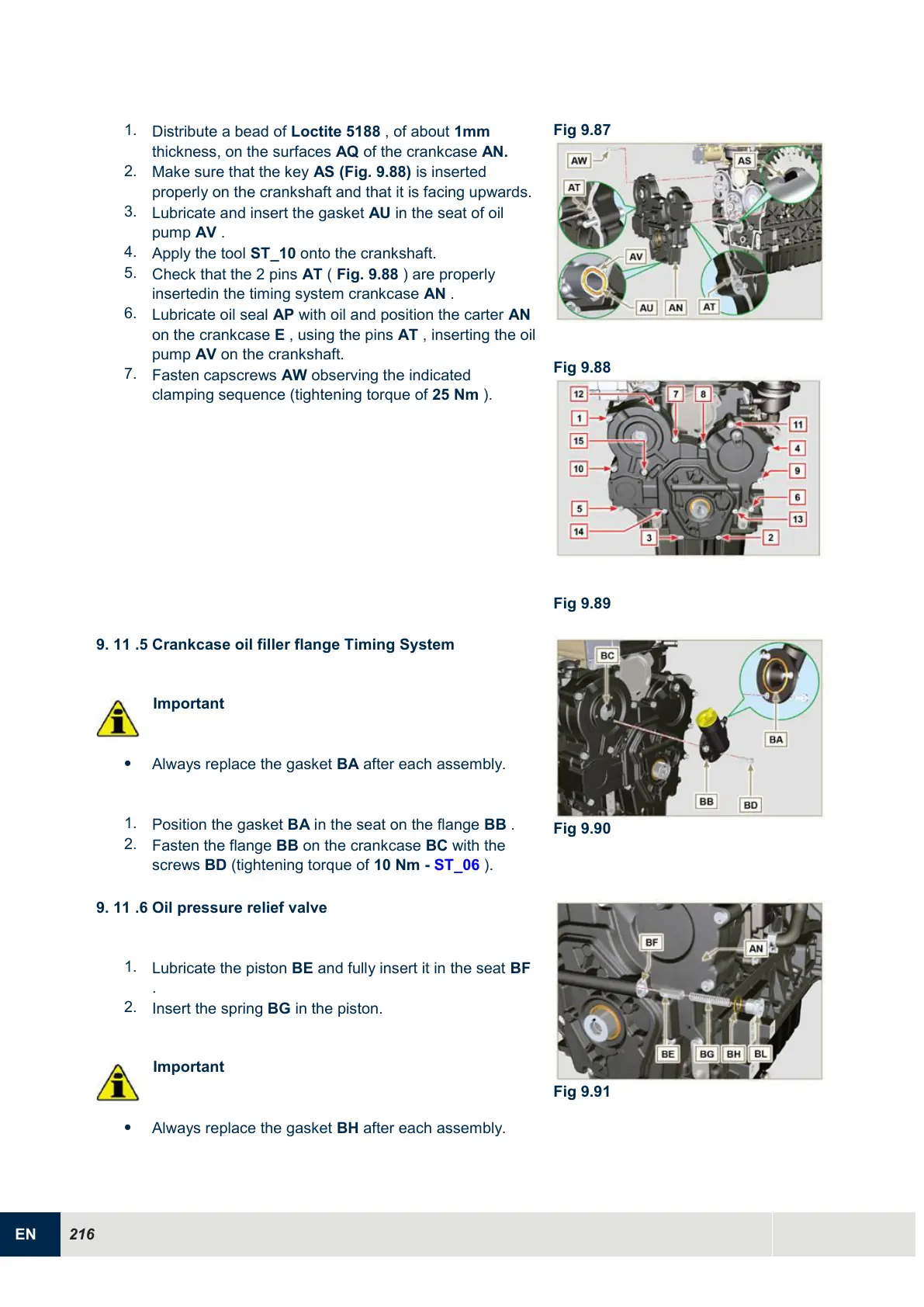
Distribute a bead of Loctite 5188 , of about 1mm
thickness, on the surfaces AQ of the crankcase AN.
2.
Make sure that the key AS (Fig. 9.88) is inserted
properly on the crankshaft and that it is facing upwards.
3.
Lubricate and insert the gasket AU in the seat of oil
pump AV .
4.
Apply the tool ST_10 onto the crankshaft.
5.
Check that the 2 pins AT ( Fig. 9.88 ) are properly
insertedin the timing system crankcase AN .
6.
Lubricate oil seal AP with oil and position the carter AN
on the crankcase E , using the pins AT , inserting the oil
pump AV on the crankshaft.
7.
Fasten capscrews AW observing the indicated
clamping sequence (tightening torque of 25 Nm ).
9.
11 .5 Crankcase oil filler flange Timing System
Important
Always replace the gasket BA after each assembly.
1.
Position the gasket BA in the seat on the flange BB .
2.
Fasten the flange BB on the crankcase BC with the
screws BD (tightening torque of 10 Nm - ST_06 ).
9.
11 .6 Oil pressure relief valve
1.
Lubricate the piston BE and fully insert it in the seat BF
.
2.
Insert the spring BG in the piston.
Important
Always replace the gasket BH after each assembly.

 Loading...


