Important
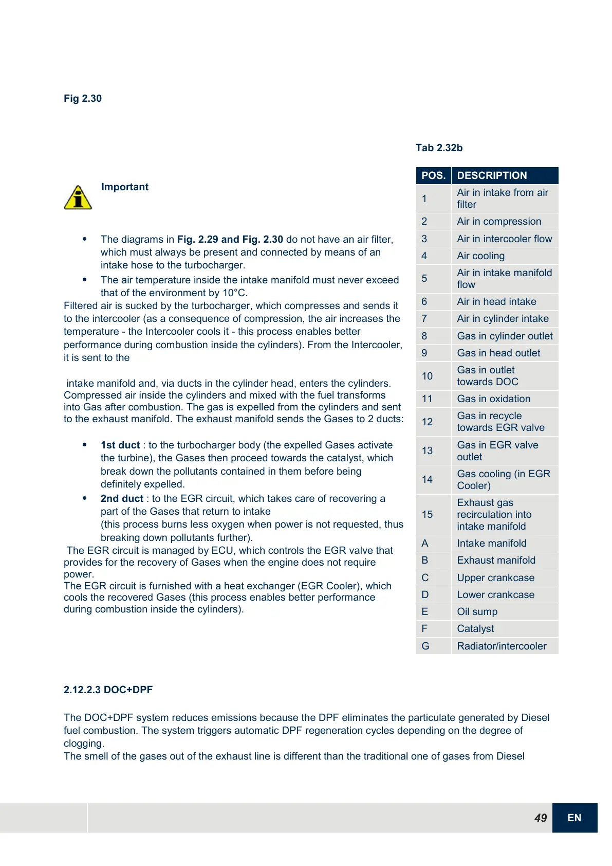
The diagrams in Fig. 2.29 and Fig. 2.30 do not have an air filter,
which must always be present and connected by means of an
intake hose to the turbocharger.
The air temperature inside the intake manifold must never exceed
that of the environment by 10°C.
Filtered air is sucked by the turbocharger, which compresses and sends it
to the intercooler (as a consequence of compression, the air increases the
temperature - the Intercooler cools it - this process enables better
performance during combustion inside the cylinders). From the Intercooler,
it is sent to the
intake manifold and, via ducts in the cylinder head, enters the cylinders.
Compressed air inside the cylinders and mixed with the fuel transforms
into Gas after combustion. The gas is expelled from the cylinders and sent
to the exhaust manifold. The exhaust manifold sends the Gases to 2 ducts:
1st duct : to the turbocharger body (the expelled Gases activate
the turbine), the Gases then proceed towards the catalyst, which
break down the pollutants contained in them before being
definitely expelled.
2nd duct : to the EGR circuit, which takes care of recovering a
part of the Gases that return to intake
(this process burns less oxygen when power is not requested, thus
breaking down pollutants further).
The EGR circuit is managed by ECU, which controls the EGR valve that
provides for the recovery of Gases when the engine does not require
power.
The EGR circuit is furnished with a heat exchanger (EGR Cooler), which
cools the recovered Gases (this process enables better performance
during combustion inside the cylinders).

 Loading...


