OPERATION DETAILED CONTROLS AND GAUGES
3-153
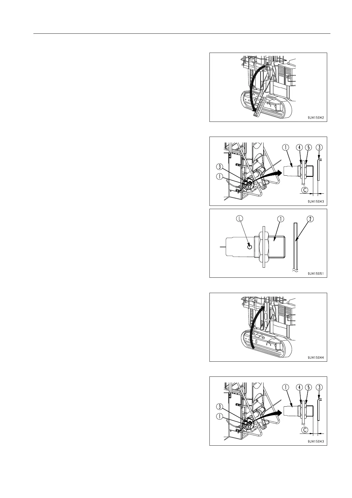
3. Lower the hydraulic ladder. For details, see “When Lower-
ing Ladder (Setting to Position for Use) (3-151)“.
4. Cover the front of proximity switch (1) installed to the
hydraulic ladder with steel plate (2) and check that actua-
tion display lamp (L) lights up.
q If actuation display lamp (L) lights up
Proximity switch (1) is working properly, so adjust as
follows to make actuating display lamp (L) light up cor-
rectly.
q If actuation display lamp (L) does not light up
There is probably a problem with proximity switch (1),
so change the combination of the connectors. For
details, see “Action When Proximity Switch Has Failed
(3-154)“.
5. Stow the hydraulic ladder. For details, see “When Raising
Ladder (Setting to Stowing Position) (3-151)“.
6. Adjust with adjustment nuts (4) and (5) of proximity switch
(1) so that clearance (C) between proximity switch (1) and
plate (3) installed to hydraulic ladder is 4-6 mm.