LOADING SHOVEL EXPLANATION OF COMPONENTS
7-3
EXPLANATION OF COMPONENTS 7
SWITCHES 7
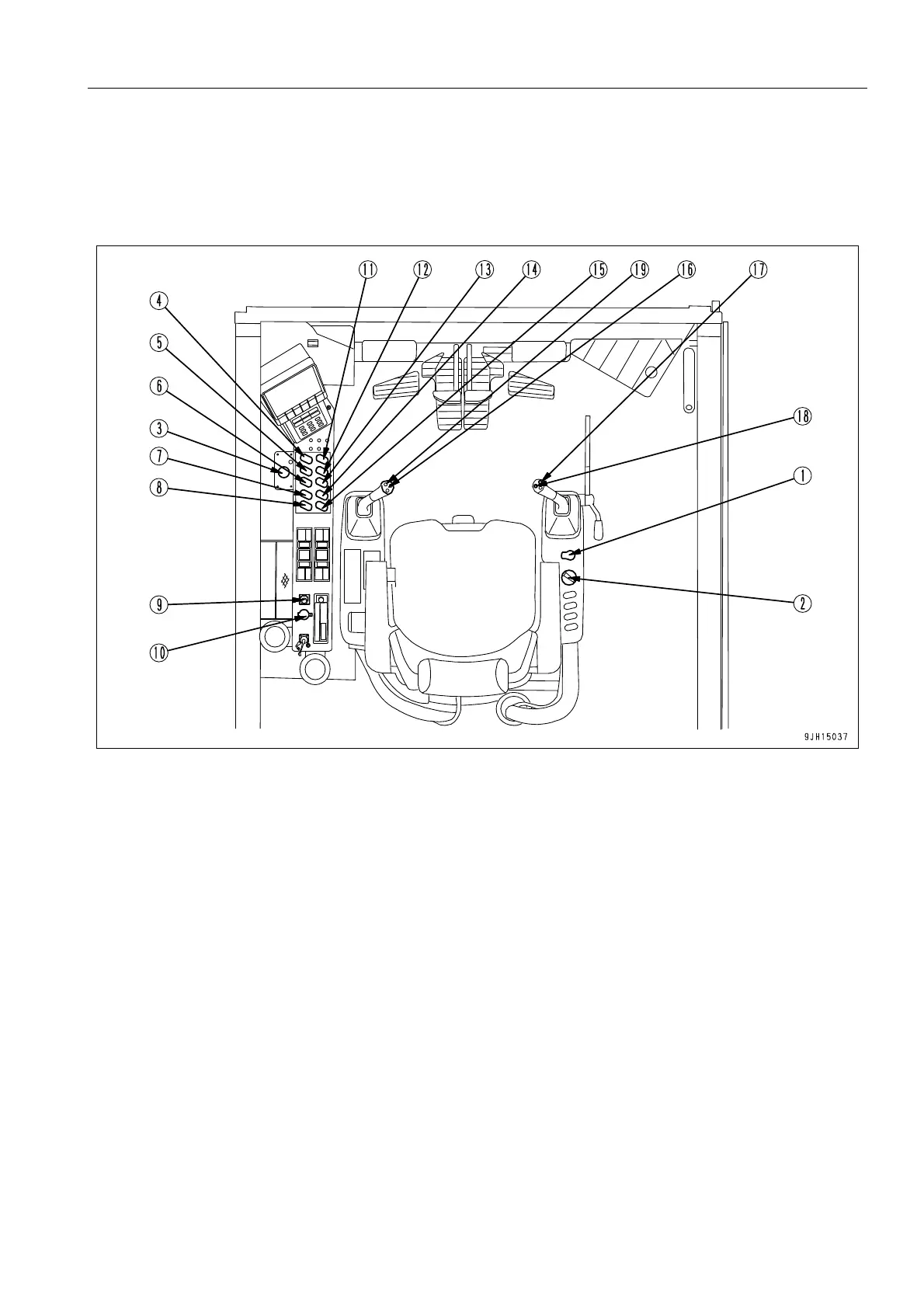
The following explanation contains details of only the switches that are different from the standard specification
machine (backhoe specification machine).
For explanation of switches (1) to (16), see “SWITCHES (INSIDE OPERATOR'S CAB) (3-75)“.
(1) Starting switch (11) Rotating lamp switch (if equipped)
(2) Fuel control dial (12) Greasing mode selector switch
(3) Engine emergency stop switch (13) Machine push-up switch
(4) Service center switch (if equipped) (14) Boom shock-less limit switch
(5) Room lamp switch (15) Swing lock switch
(6) Additional lamp switch (16) Truck counter switch
(7) Working lamp switch (17) Horn switch
(8) Step light switch (18) Bottom dump OPEN switch
(9) Cigarette lighter (19) Bottom dump CLOSE switch
(10) 12V power supply