OPERATION DETAILED CONTROLS AND GAUGES
3-155
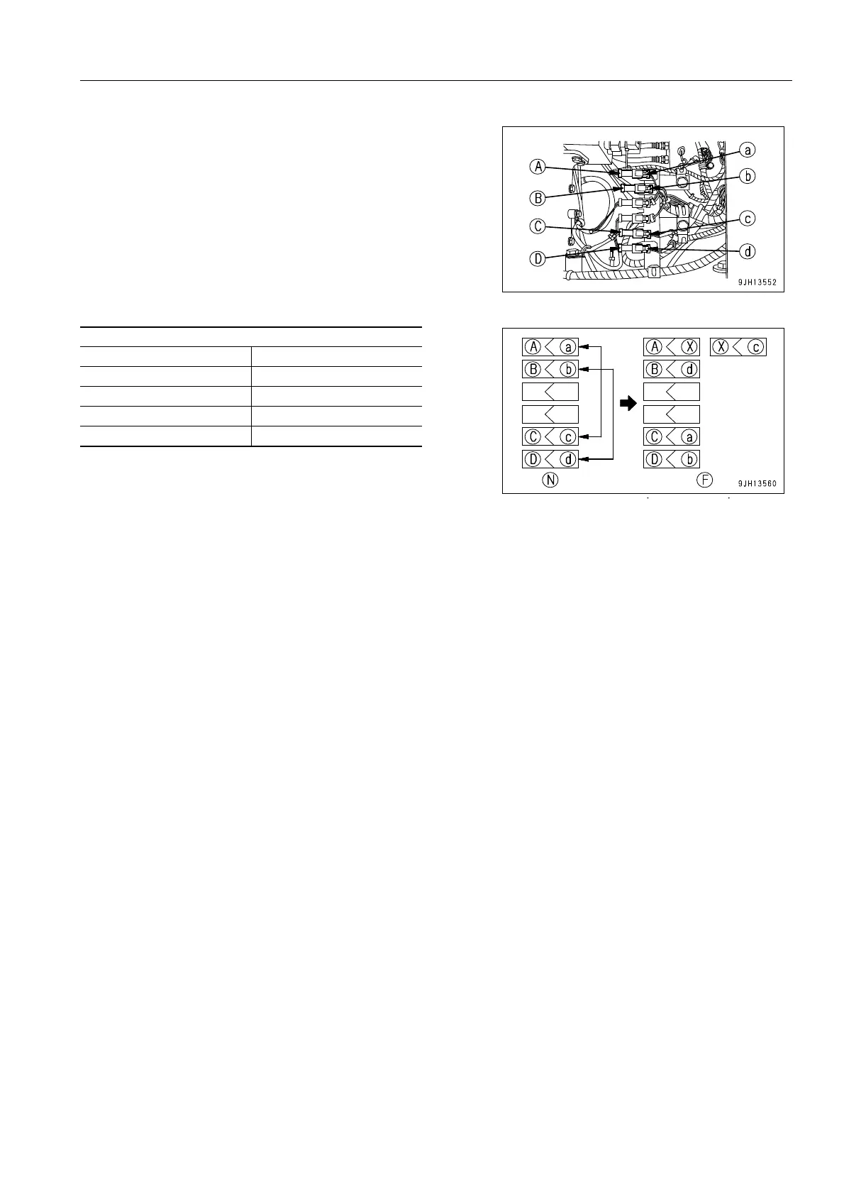
4. Interchange connector (a) and connector (c).
Connect connector (a) to connector (C), and cover connec-
tor (c) and connector (A) with cap (X).
5. Interchange connector (b) and connector (d).
Connect connector (b) to connector (D), and connect con-
nector (d) to connector (B).
6. Connect the negative (-) terminal of the battery, start the engine, then check that it is possible to operate the
travel, swing, and work equipment.
If they cannot be operated, there is probably some other cause, so ask your Komatsu distributor to carry out
investigation.
Connector connection chart
When normal (N) When failed (F)
(A) - (a) (A) - (X), (X) - (c)
(B) - (b) (B) - (d)
(C) - (c) (C) - (a)
(D) - (d) (D) - (b)