OPERATION MACHINE OPERATIONS AND CONTROLS
3-177
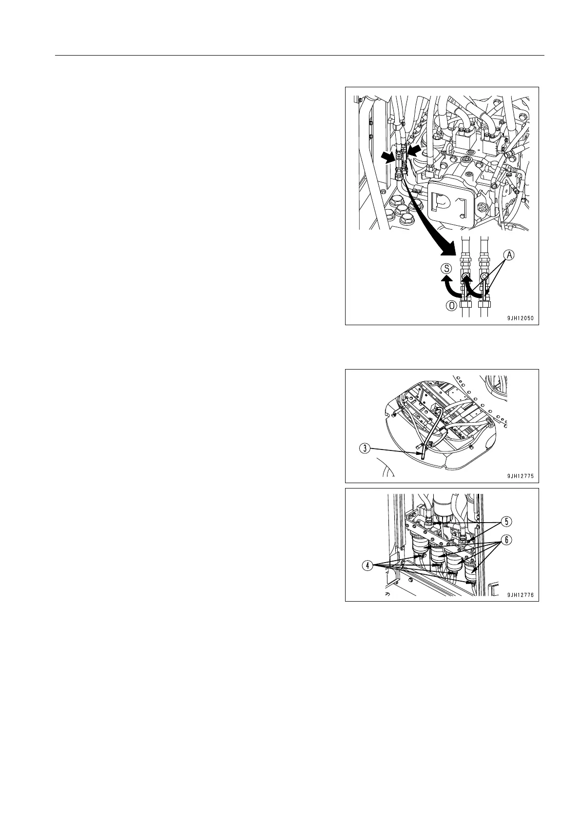
2. Pull up fuel shut-off lever (A) installed at the front of the
main pump inside the pump room to shut off the fuel supply
circuit from the fuel tank.
(S): Shut off
(O): Open
3. How to drain water
1) Put a container to catch drain water under drain hose (3)
provided in the lower part of the revolving frame.
2) Loosen plug (4) and drain the water.
3) If the water cannot be drained, remove air intake plug (5).
[Width across flats: 14 mm (0.6in)]
The water will drain from plug (4).
4) When fuel starts to come out, tighten plug (4) immediately.
Tightening torque: 1.5 - 2.5 Nm (0.15 - 0.25 kgm)
5) If the inside of filter case (6) is dirty with the sediment,
wash it.
For details, see “INSPECTION OF ADDITIONAL WATER
SEPARATOR AND CLEANING OF CASING INTERIOR (4-
62)“.
6) Tighten air intake plug (5).
Tightening torque: 8.0 - 12.0 Nm (0.8 - 1.2 kgm)
4. Push down fuel shut-off lever (A) to open the fuel supply circuit.
5. After completing the water drain operation, bleed the air. Use the same procedure as when replacing the fuel
filter cartridge.
For details of the method of bleeding the air, see “Bleeding air from fuel circuit with the electric priming pump
(4-47)“.




 To Next Page