MACHINE OPERATIONS AND CONTROLS OPERATION
3-230
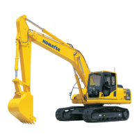
2. Remove pin (1) from the arm mounting hole and pin (2)
from the link mounting hole, then remove the bucket.
q With pin (1), remove grease piping cover (3) and
grease piping (4), then remove cover (5) and use the
removal tap in the side face of the pin to remove the
pin (both left and right).
q With pin (2), remove stopper (6) on the inside of the
link, then use the removal tap on the outside face of
the pin to remove the pin (both left and right).
After removing the pins, make sure that mud or sand does
not get on them. Dust seals are fitted at both ends of the
bushings, be careful not to damage them.
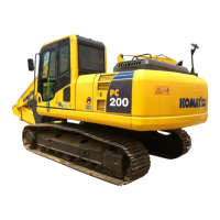
3. Align the arm with hole (A), align the link with hole (B), then
coat pins (1) and (2) with grease, and install them.
Carry out the installation in the opposite order from removal.
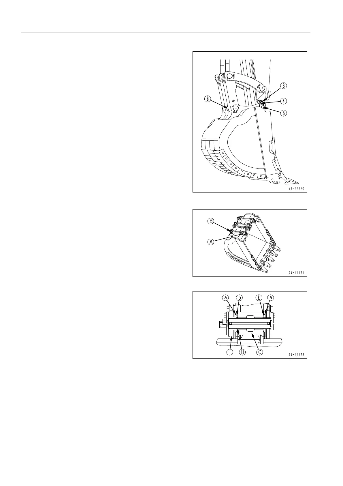
When installing the bucket, the O-ring is easily damaged, so fit
the O-ring into the groove in bushing (a) at the bucket end (E).
After inserting the pin, move the O-ring to the specified groove
(b).
After fitting the stopper bolts, stoppers, collars, and covers to
each pin, carry out greasing of the pin.
(C): Arm (D): Seal (E): Bucket