MAINTENANCE PROCEDURE MAINTENANCE
4-40
2. Within 15 seconds after stopping the engine, move each
control lever (for work equipment and travel) to the full
stroke in all directions to release the internal pressure.
3. Check that the work equipment is in a stable condition,
then set the lock lever to the LOCK position (L).
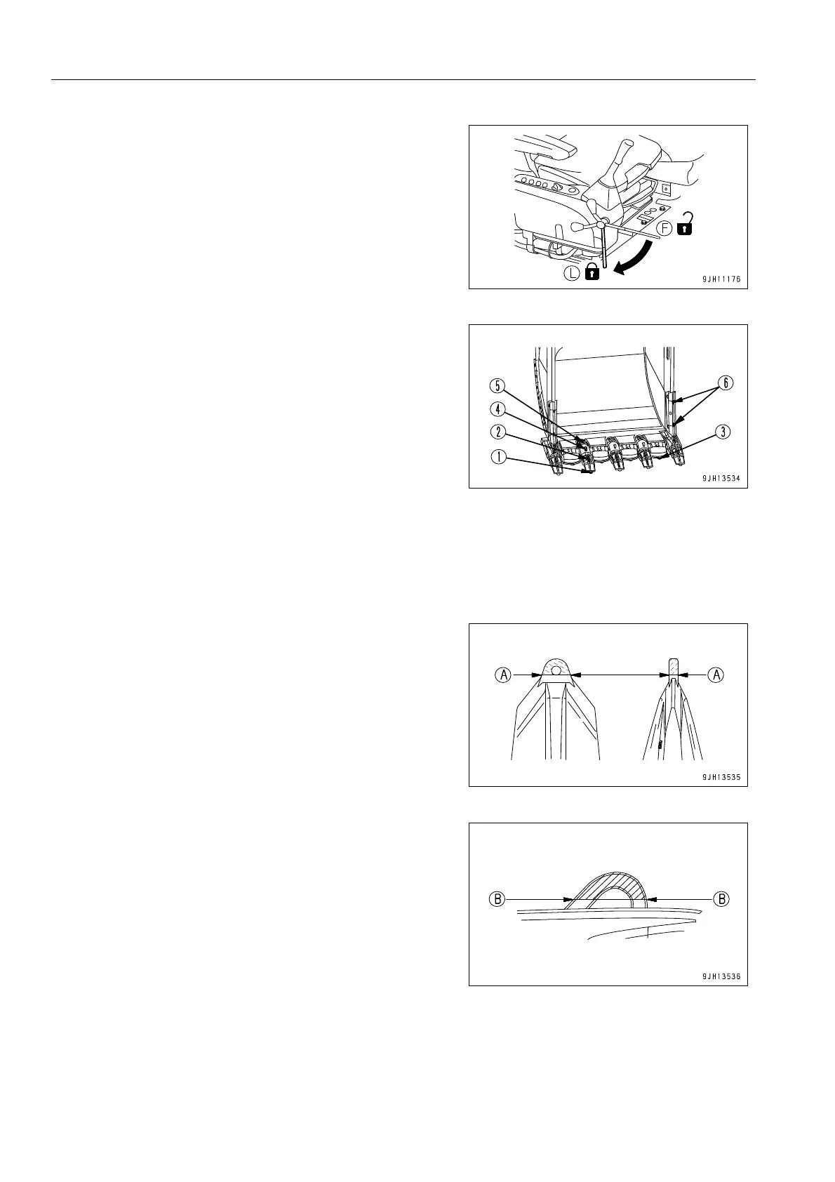
4. Preheat the slinging loop to be cut to 100-150 °C and use a
gas cutter to cut the slinging loop at each part of the
bucket.
q Tip of tooth (1), top of tooth (2), lip shroud (3), wear
cap (4), adapter (5), side shroud (6).
When cutting the slinging loop at each part of the bucket,
cut at the following cutting positions (A) - (A) or (B) - (B),
according to the shape of the loop.
In addition, when doing this, be careful that the cutting
surface does not cut into the main body of the bucket
parts.
q Cutting position (A) - (A)
This applies to tip of tooth (1), lip shroud (3), wear cap (4),
and side shroud (6).
Cut at the bottom of the hole in the lifting loop.
q Cutting position (B) - (B)
This applies to top of tooth (2) and adapter (5).
Cut at a position 10-20 mm from the main body of the
bucket part.
5. Finish the cutting surface smoothly, using a grinding machine.
6. Check that there is no crack on the cutting surface.