ATTACHMENTS AND OPTIONS HANDLING SERVICE CENTER
6-25
3. Remove the cap of PTO oil coupler (1) and connect the
force-feed pump coupler securely.
4. Start to drain and add PTO oil.
5. After completing the draining and adding of PTO oil,
remove the force-feed pump coupler.
6. Install the cap to the coupler.
7. Set drain valve (P) under the PTO case to shut position (S).
8. Check that the oil level is between the H and L marks on the dipstick. For details, see “Check Oil Level in PTO
Case, Add Oil (3-169)“.
9. After checking, insert dipstick (G).
Method of Draining, Adding Hydraulic Oil 6
q Immediately after the engine is stopped, the oil and parts are at high temperature, and this will cause
burns. Wait for the temperature to go down before starting the operation.
q When removing the cap from the oil filler, oil may spurt out, so turn it slowly to release the internal
pressure, then remove it.
q When removing holder cover of the strainer, the cover is under pressure from spring and may fly out,
so loosen the 4 bolts gradually.
q Oil refill capacity: 1301.1 liter
q Prepare a handle for socket wrench set
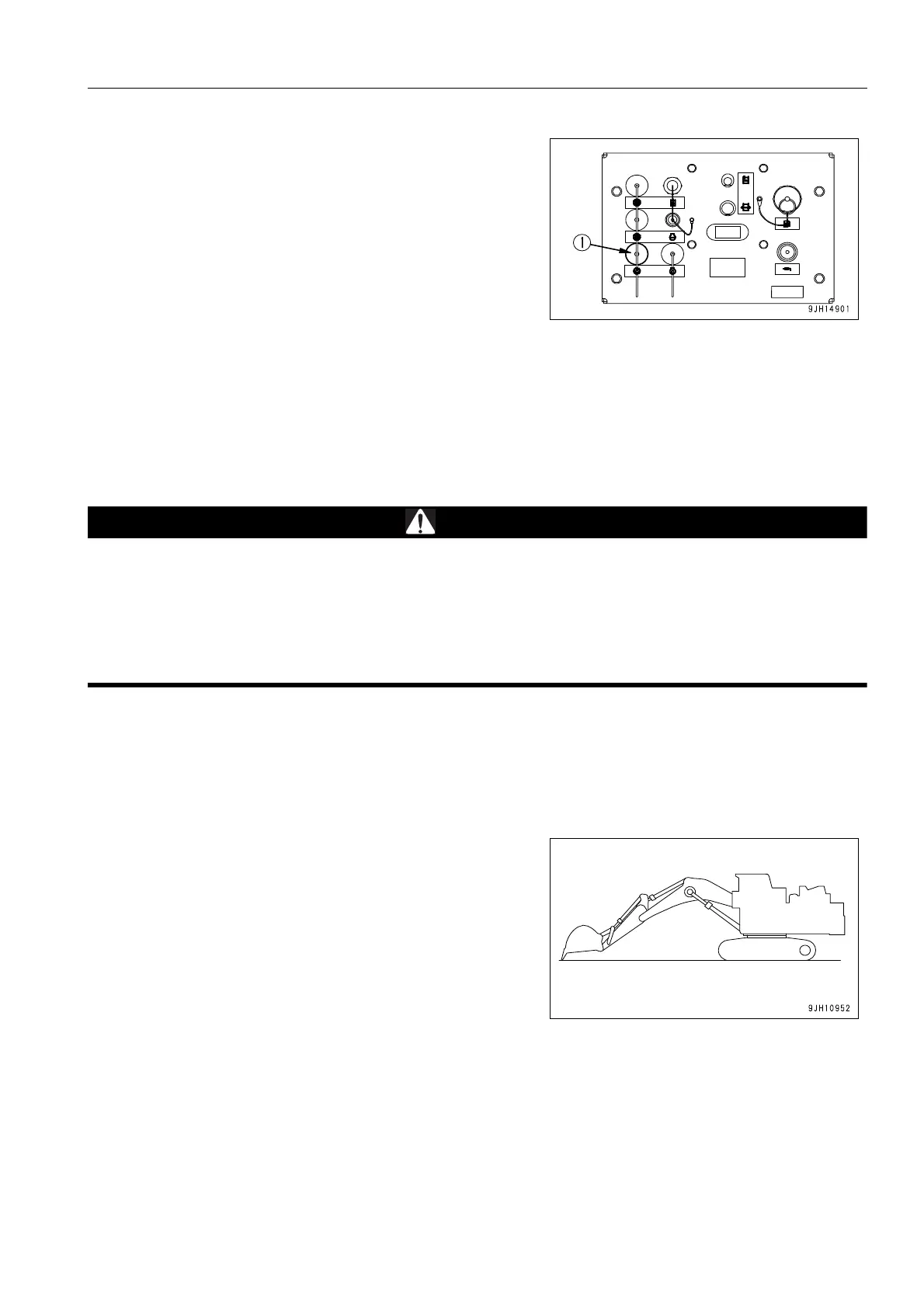
1. If the machine is not in the posture shown in the diagram
on the right, start the engine, run the engine at low speed,
lower the blade to the ground, retract the arm and bucket
cylinders, lower the boom and set the bucket teeth in con-
tact with the ground, then stop the engine.
2. Within 15 seconds after stopping the engine, turn the start-
ing switch to the ON position and operate all control levers
(work equipment, travel) and pedals (offset) fully in all
directions to release the internal pressure.
3. Set the lock lever to the LOCK position and stop the
engine.