HANDLING SERVICE CENTER ATTACHMENTS AND OPTIONS
6-34
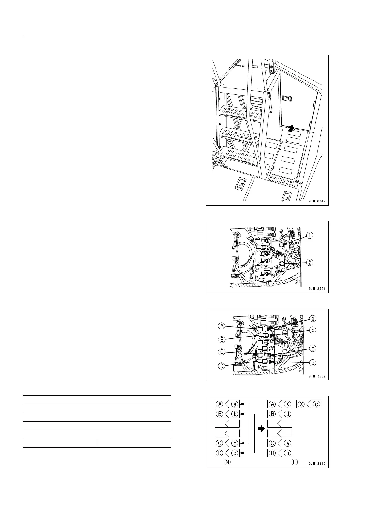
2. On the right side inside the cab base room there is the con-
nector for the PPC (proportional pressure control pilot)
lock.
3. Remove bolts (1) and (2) of the clamp holding the connec-
tor cable.
4. Interchange connector (a) and connector (c).
Connect connector (a) to connector (C), and cover connec-
tor (c) and connector (A) with cap (X).
5. Interchange connector (b) and connector (d).
Connect connector (b) to connector (D), and connect con-
nector (d) to connector (B).
Connector connection chart
When normal (N) When failed (F)
(A) - (a) (A) - (X), (X) - (c)
(B) - (b) (B) - (d)
(C) - (c) (C) - (a)
(D) - (d) (D) - (b)
 Loading...