BA 35101/02/ 03 EN – Edition 1.0 * 35101_02_03b340.fm 3-89
Operation
Specific safety instructions for picking up loads with the pallet forks
• Always lock the control lever for the 3rd control circuit when working with the pallet
forks –seeOperating and securing the 3rd control circuit on page 3-63.
• Always follow the Load diagram for pallet forks. Never exceed maximum load!
• Follow the special instructions in the Operator's Manual of the pallet forks!
• Approach the material as closely as possible!
• Always approach the material with the machine wheels in straight-ahead position!
• Always load on firm and level ground with sufficient load-bearing capacity only (for a
fully loaded machine)!
• Never raise a load with only one fork arm!
• Maintain a distance of a minimum 6 m between the loader unit/load and overhead lines!
• Before starting work, make sure the fork arms on the fork frame are safely locked!
• Never operate the loader unit and the attachments at higher machine speed!
• Never leave the machine with the load raised!
• Always transport the load close to the ground!
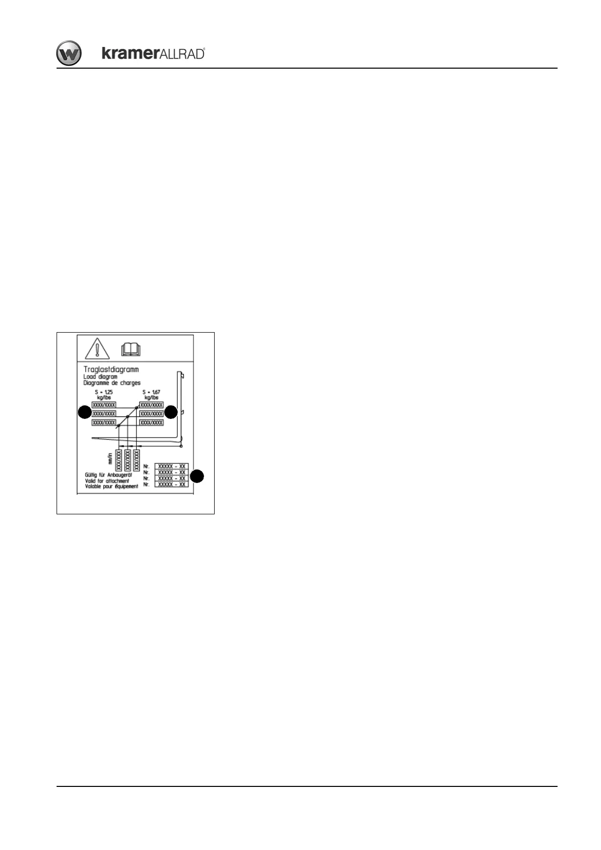
Load diagram for pallet forks
The load diagram is located in the cab on the front window, values are calculated for the
respective machine model (– see chapter 1 “Attachments with authorised material densi-
ties” on page 1-5).
• Do not exceed the maximum loads stated, otherwise machine stability is no longer
ensured.
• The framed row of numbers A on the left states the maximum load for applications on
level ground (stability s = 1.25).
• The framed row of numbers B on the right states the maximum load for off-road appli-
cations (stability s = 1.67).
• The maximum load is a function of the distance (load distance) of the load centre to the
fork frame C (lower row of figures).
• Take this into account also when using fork arm extensions!
Example:
• Safety factor for off-road applications S = 1.67 (framed row of figures on the right B)
➥ Load distance = 600 mm (vertical centre line).
• The maximum load C amounts to xxxx! (Intersection of the middle vertical line with the
slanting line)
• Pallet forks payloads – see chapter 6 “Payloads” on page 6-15
C
B
Fig. 140: Load diagram
A