6-8 BA 35101/02/03 EN – Edition 1.0 * 35101_02_03b610.fm
Specifications
6.9 Electrical system
Electric units
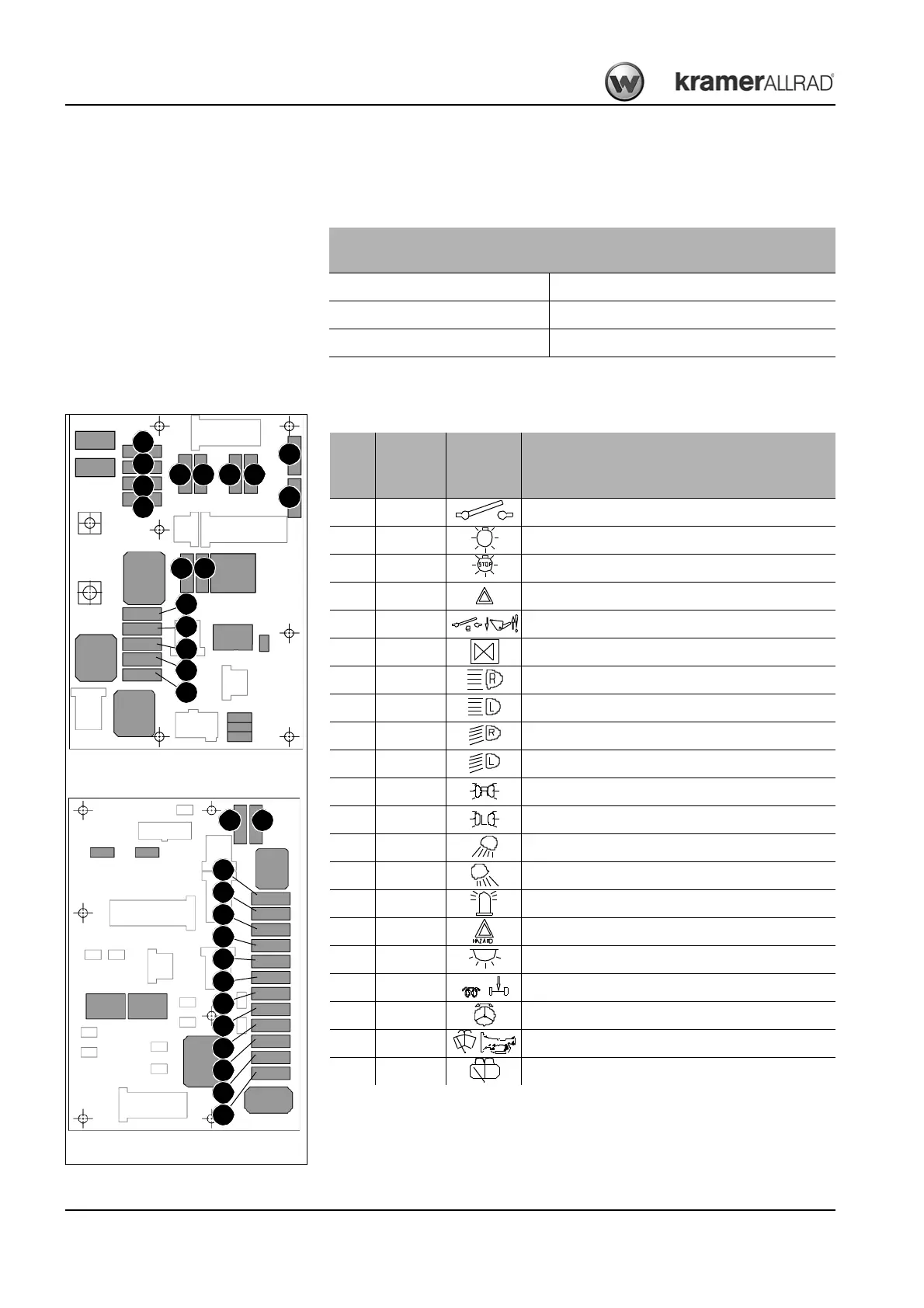
Fuses
The fuses are installed on the board under the switch panel.
Wheel loader models
352-01 / 352-02
Alternator 12 V 95 A
Starter 12 V 2.3 kW
Battery 12 V 88 Ah
Fig. 195: Fuses on right-hand side board
F 9F10
F11
F12
F14
F 1
F 2
F 3
F 4
F 7F 8
Fig. 194: Fuses on left-hand side board
F13
F 5
F 6
F15
F17
F16
F28F27
F24
F18
F26
F23
F29
F22
F19
F25
F27
F21
F28
F20
No.
Rated
current
(A)
Symbol Protected circuit
F1 15 Front socket
F2 15 High and low beam
F3 7.5 Brake lights
F4 7.5 Turn indicators
F5 3 Electronics: front socket
F6 15 Solenoid valves
F7 7.5 High beam (right)
F8 7.5 High beam (left)
F9 7.5 Low beam (right)
F10 7.5 Low beam (left)
F11 5 Parking light (right)
F12 5 Parking light (left)
F13 15 Front working light
F14 15 Rear working light
F15 10 Rotating beacon
F16 7.5 Hazard warning lamp
F17 7.5 Interior light (cab)
F18 3 Glow control unit, axle sensors
F19 7.5 Steering system
F20 15 Front wiper, horn
F21 10 Rear wiper