3-96 BA 35101/02/03 EN – Edition 1.0 * 35101_02_03b340.fm
Operation
Operation of front/rear additional control circuits
Operation of front/rear additional control circuit
.
Operation of rear additional control circuit (tipping trailer connection)
No operation of attachments at the front and rear quick couplers at the
same time!
• Uncouple the attachment if it is not used
• See the Operator's Manuals of the attachment manufacturers for installing
and operating the attachments!
9796
A B
E
C
V
H
D
G
K
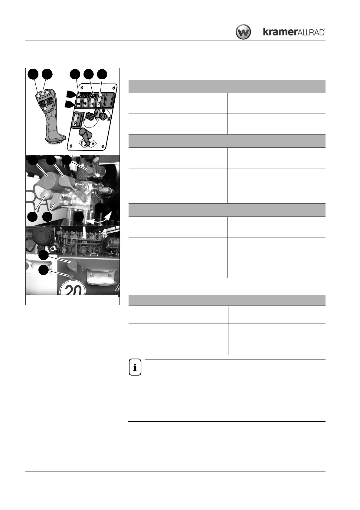
Fig. 150: Operation of the additional control circuit (option)
F
94
B
A
105104
Operation of front or rear additional control circuit (38 l)
Set changeover tap D to position V or H
The front or rear coupling connections are
enabled
Slide the lock on switch 96 downwards and
press the switch to position B
Pressure (38 l) is applied to coupling con-
nections A+B (front) or G+K (rear)
Operation of front or rear additional control circuit (115 l)
Set changeover tap D to position V or H
The front or rear coupling connections are
enabled
Slide the lock on switch 94 downwards and
press the switch to position B
Slide the lock on switch 96 downwards and
press the switch to position B
Pressure (115 l) is applied to coupling con-
nections A+B (front) or G+K (rear)
Operation of front additional control circuit (additional functions)
Slide the lock on switch 96 downwards and
press the switch to position B
The additional control circuit is enabled
Press tip switch 104 on the control lever
Pressure is applied to coupling
connection F
Press tip switch 105 on the control lever
Pressure is applied to coupling
connection E
Operation of rear additional control circuit (tipping trailer)
Set changeover tap D to position H
Rear tipping trailer connection G+K is
enabled
Press switch 97 up or down
To raise the tipping trailer = tip switch posi-
tion B
To lower the tipping trailer = tip switch
position A