LumaSMART
®
User Manual IEC 61850 Protocol Testing • 104
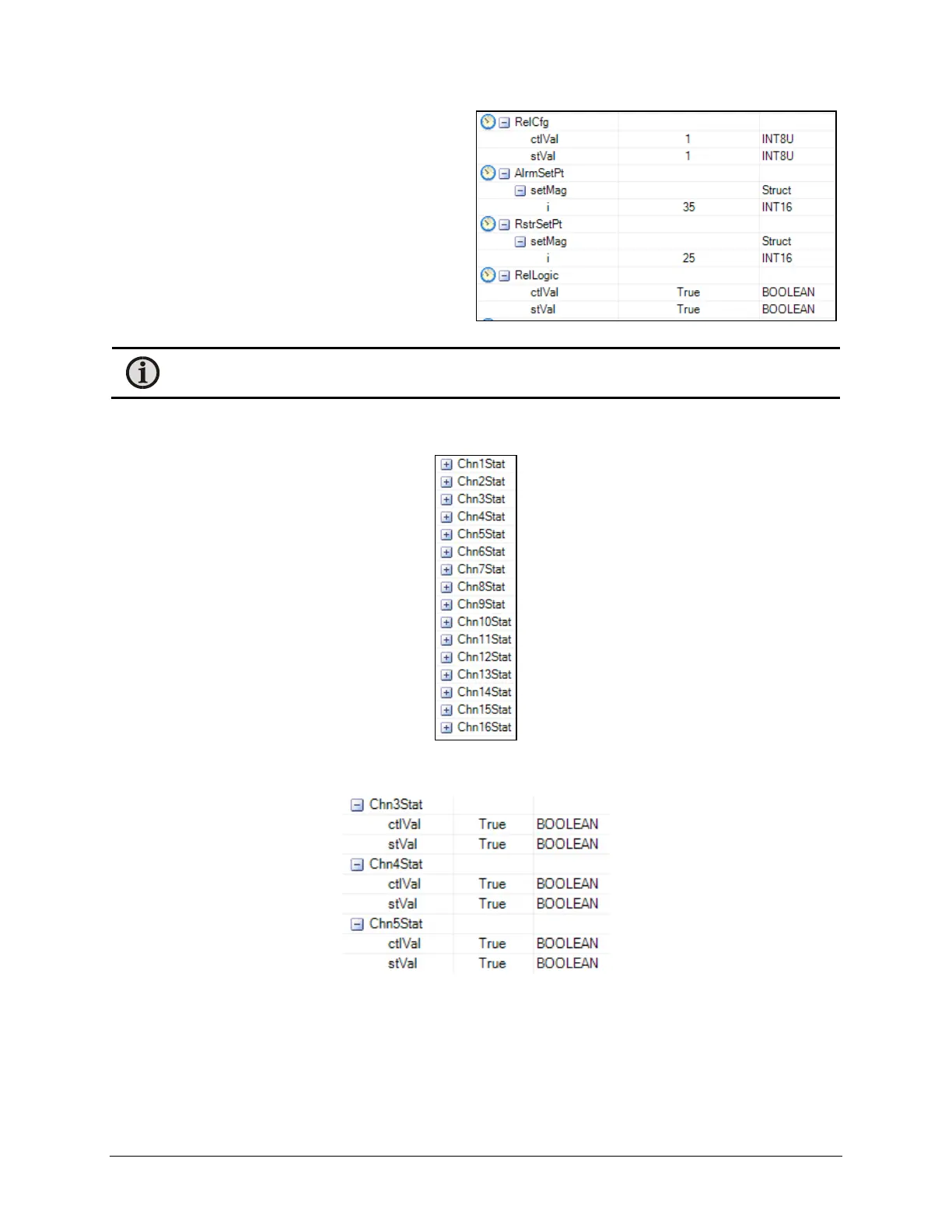
Follow this procedure to change the follow entries to
the indicated value.
R4CSWI4 > AlrmSetPt > setMag > i to 35 °C (Alarm
Setpoint)
R4CSWI4 > RstrSetPt > setMag > i to 25 °C (Restore
Setpoint)
R4CSWI4 > RelLogic > ctlVal to ‘True’ (specify the ‘OR’
function)
After refreshing the modified entries, the display
should show:
Note: The clock icon to the left of the field names is present since the Start Polling was established to
automatically Refresh the information.
Once the relay is configured, associate the temperature channels that will drive the relay function. Associated with
each relay branch is a set of ChnXStat controls, as shown below:
For this example, Channels 3, 4, and 5 are set to drive this relay. Expand the entries using ChnxStat for entries
where x is 3, 4, and 5. The display should then look like this:
Entry Expanded
As before, change the following entries to associate the channels to the relay:
R4CSWI4 > Chn3Stat > ctlVal to ‘True’ (associate channel 3 with relay 4)
R4CSWI4 > Chn4Stat > ctlVal to ‘True’ (associate channel 4 with relay 4)
R4CSWI4 > Chn5Stat > ctlVal to ‘True’ (associate channel 5 with relay 4)

 Loading...