LumaSMART
®
User Manual Installation of the LumaSMART® Controller • 50
4.3.3 Relay Output Wiring
The LumaSMART includes 0, 8, or 16 programmable Form-C relays and one system status Form-C relay. Use the MC
1.5/8-SFT-3.81 connector from Phoenix Contact (Part # 1827716) to make the external connection to the relay
connectors. The optional ferrule is Part # 3200519.
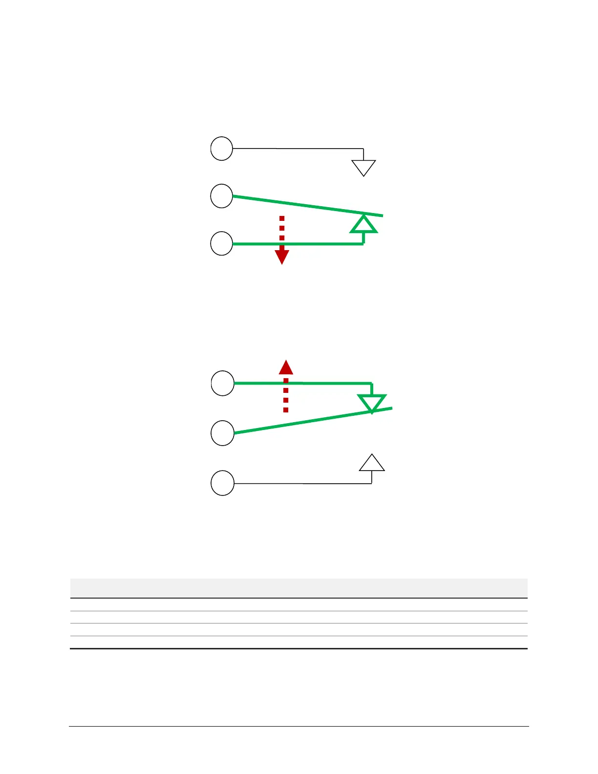
Form-C Relay in Deenergized (Off State)
Form-C Relay in Energized (On) State
System Status Relay
This relay provides an indication of overall LumaSMART health. This relay is operated in a FailSafe mode, meaning
that when there are no system issues, it is Energized, and only Deenergized during a fault condition. The logic table
is as follows:
System Condition Relay State
Power Restored – System Booting
System Booted – Fault Exists

 Loading...