LumaSMART
®
User Manual Introduction • 14
2.1.1 System Organization
The figure below shows the LumaSMART controller organization. The optical components, microprocessor, and a
Digital Signal Processor (DSP) are contained in the Fiber Optic Thermometer (FOT) module, which sends output
(temperature data and several status signals) to the CPU and sets analog output levels. The CPU then displays data
on the LCD display, controls the relay outputs, and sends the data through the communication ports.
LumaSMART Controller Organization
2.2 Theory of Operation
LumaSMART uses LumaSense Technologies’ patented Fluoroptic
®
technology, which is based on a temperature-
sensitive phosphorescent sensor attached to the end of an optical fiber. Pulses of light transmitted down the fiber
optic probe excite the sensor and causes it to phosphoresce. The
Digital-Signal-Processor (DSP)-based electronics detect and calculate the decay time of this phosphorescence after
each pulse. This decay time varies precisely with the sensor temperature, providing the basis for accurate
temperature measurement. The LumaSMART controller achieves ± 2.0 °C when using the LumaSense DipTip
RuggedProbe and QualityProbe sensors.
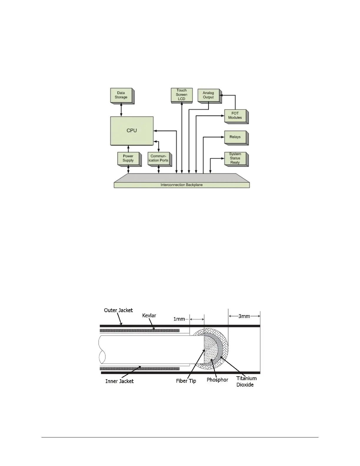
2.2.1 Temperature Sensor
LumaSMART temperature measurement is based on the phosphorescence decay time of a special phosphor
sensor, located at the end of a fiber optic cable. This specific sensor is basic to the LumaSMART function. The figure
below illustrates temperature sensor construction.
Probe Design
Light generated by an excitation LED is routed through a probe extension and connectors, where it falls on the
phosphor material at the probe tip. When stimulated with red light, the phosphor emits radiation over a broad

 Loading...