LumaSMART
®
User Manual Installation of the LumaSMART® Controller • 51
The Fault conditions include:
System Condition Cause
Communications with FOT 1
Communications with FOT 2
Communications with FOT 3
Communications with FOT 4
Backup Clock Battery need replacement
File error with the Data Log
Fault with the default RS232 Port
Fault with the secondary RS232/485 Port
Fault on the Ethernet Port
Shutdown/Reboot is in progress
Fault within selected Protocol
A date/time stamped log is generated when the System Status Relay changes states. See Section 5.2.6.5 for System
Status Relay History.
4.3.4 Optional Communication Wiring
The Ethernet connector is the normal standard. Shielded Ethernet cable must be used. By default, the IP address
for the Ethernet connection is set to a static non-routable, local host, loopback IP address of 127.0.0.1. Before the
system can communicate to the outside world, the static IP address must be set to match your network
topology,see Section 5.2.6.7 for Select Interface and Setup TCP/IP Ethernet Interface Parameters
.
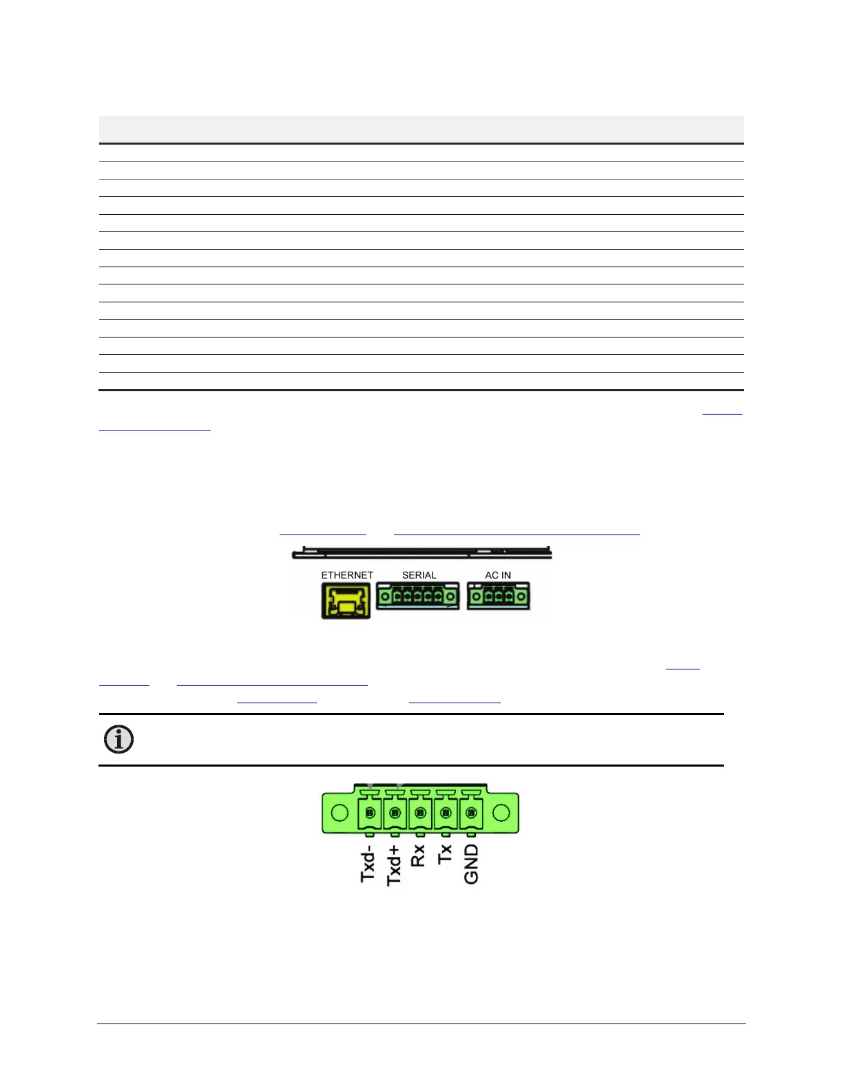
LumaSMART Communication Connections
The Txd-/Txd+ pins are used for RS485 communications (2-wire/Half-Duplex). See Section 5.2.6.7 for
Select
Interface and Setup RS485 Interface Parameters. The Rx/Tx pins are RS232 and are used for the dedicated ASCII
interface. See Chapter 9 Data Manager and Chapter 10 User Commands.
Note: Always connect the GND pin between the LumaSMART and the report communications
device.
Communication Wiring Diagram
Use the MC 1.5/8-SFT-3.81 connector from Phoenix Contact (Part # 1827732) to make the external connection to
the communication port. The optional ferrule is Part # 3200519.

 Loading...