LumaSMART
®
User Manual Installation of the LumaSMART® Controller • 47
1. Using the red Viton
®
caps supplied with the cable, cover the connector ends during fiber optic cable
installation.
2. Tape the pull wire to at least 152.5 mm (6 in) of the outside fiber optic cable and then pull the fiber optic
cable through the conduit. (Add conduit diameter).
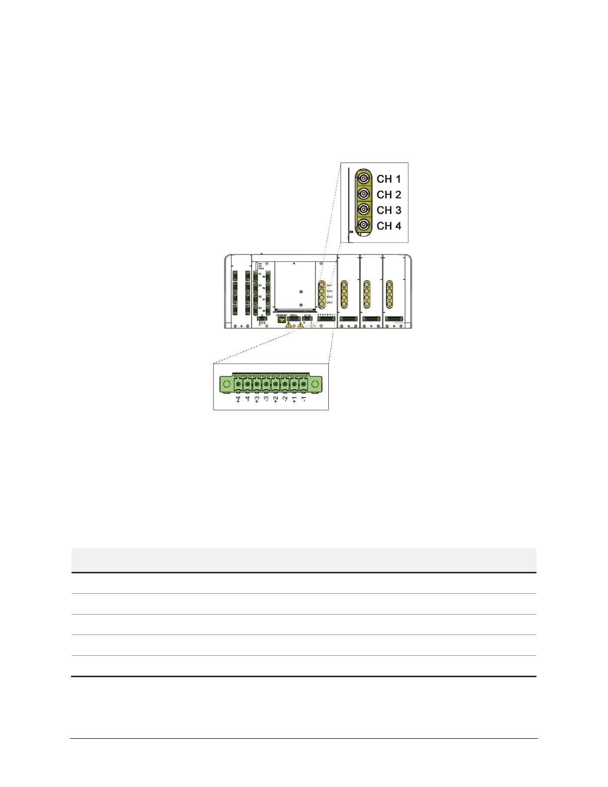
3. Label and connect all cables through the bottom of the LumaSMART controller. Fiber Optic probe
channels start from back to front (Channel 1 through Channel 4).
LumaSMART Controller FOT Connections (Front Facing Upward)
4. Store the excess fiber optic cable in 152.5 mm (6 in) diameter loops.
4.3 Installing the Electrical Wiring
The following are directions to electrically wire the LumaSMART power, outputs and infrastructure
communication. The table below outlines the standard configuration, as well as the optional infrastructure
communication.
Table 5: LumaSMART Standard Configuration
Characteristic Specification
Analog Output 4 to 20 mA or 0 to 1 mA
Programmable Relays 0, 8 or 16 Form-C
System Status Relay 1 Form-C
Optional (Infrastructure) Communication RS485, RS232, Ethernet
Protocols IEC 61850, Modbus, DNP3 or ASCII

 Loading...