LumaSMART
®
User Manual Using the Software • 65
Relay Configuration Editor
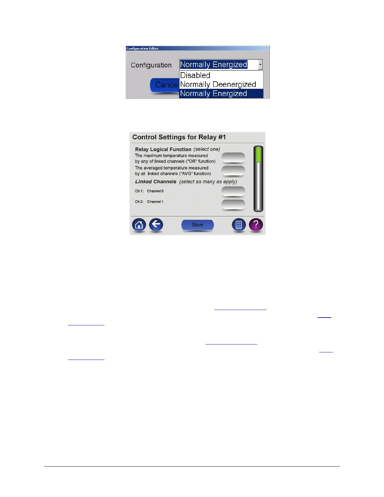
• Control Settings—Displays a screen where you can configure the relay’s logical function and associated
channels.
Control Setting Screen
o The “OR” logical function sets the system to alert when any of the selected channels passes the
energize set-point temperature. The “AVG” logical function sets the system to alert when the
average temperature of the selected channels passes the energize setpoint temperature.
o Under Linked Channels, select the channels you would like the logical function to apply to. Be sure to
press the Save button to apply your settings before leaving the menu screen.
• Alarm setpoint—is the temperature at which the relay will go into its Non-Normal state. If configured as
Normally Energized, it will De-energize (See Section 4.3.3 Relay Output Wiring
Figure: Form-C Relay in
Deenergized (Off) State). If configured as Normally Deenergized, it will Energize (See Section 4.3.3 Relay
Output Wiring Figure: Form-C Relay in Energized (On) State).
• Restore setpoint—is the temperature at which the relay will go into its Normal state. If configured as
Normally Energized, it will Energize (See Section 4.3.3 Relay Output Wiring
Figure: Form-C Relay in
Energized (On) State). If configured as Normally Deenergized, it will De-energize (See Section 4.3.3 Relay
Output Wiring Figure: Form-C Relay in Deenergized (Off) State).
Analog Outputs
The Analog Outputs overview screen shows a list of the channels and their current analog output configurations.
The analog output configuration was set during the manufacture phase and cannot be changed.

 Loading...