LumaSMART
®
User Manual IEC 61850 Protocol Testing • 103
7.4 Sample Relay Setup
In the example on the right, Relay 4 will be setup as follows:
1. Enabled – Normally Deenergized
2. Alarm set point set to 35 °C
3. Restore set point to 25 °C
4. Temperature monitoring of channels 3 through 5 will drive the relay control.
5. The logic will be set to ‘OR’
Refer to Section 5.2.1.4 Relay Setup and Section 7.8 IEC61850 Register Maps
at the end
of this section for more information.
The TMW Hammer allows the user to navigate to a specific nodes by using the and
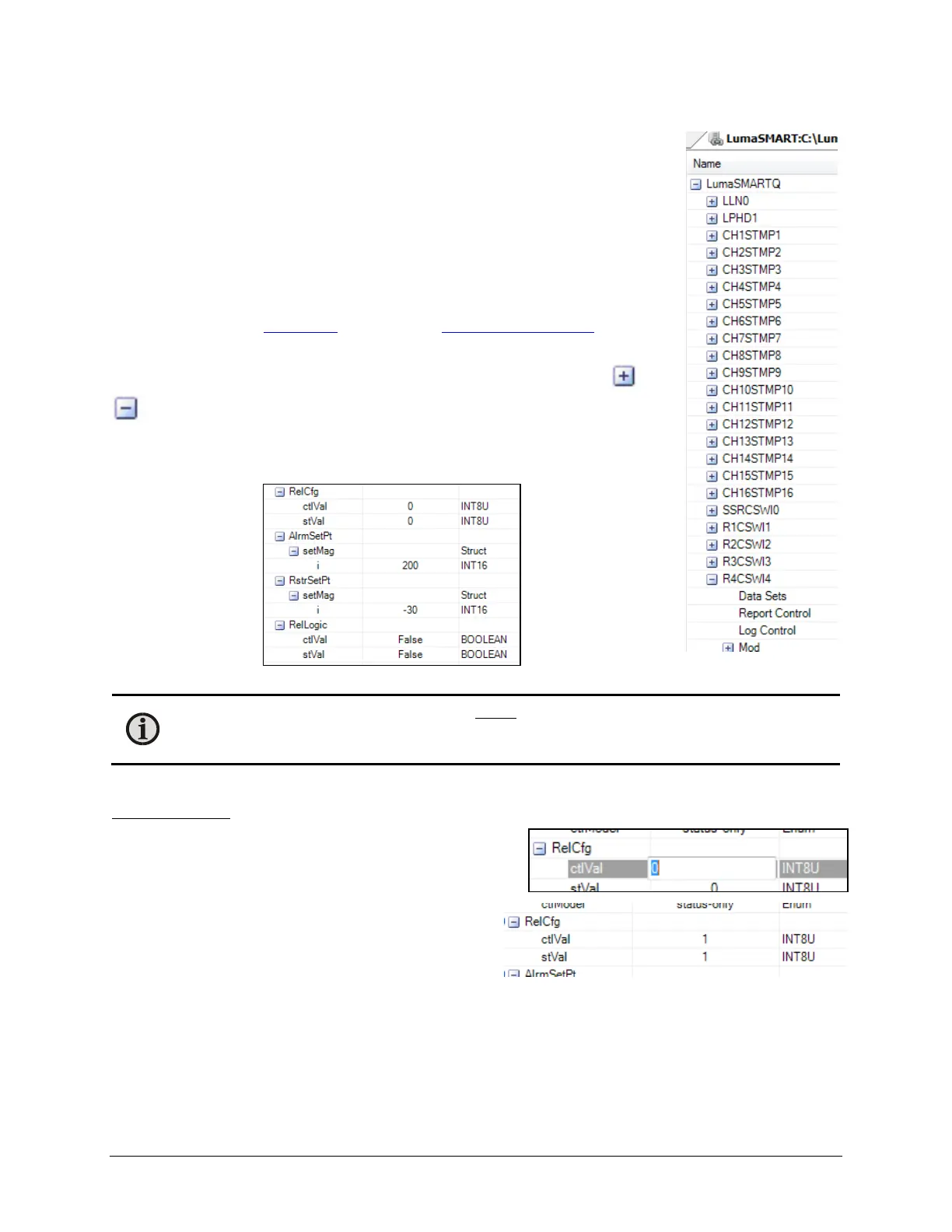
buttons in the main window. Shown below is the result of navigating to Relay 4
(node R4CSWI4 where 4 in the relay number).
You will find additional fields to expand below this relay, as shown below:
Note: The values in this window are static and do not automatically refresh. To refresh a value, right-
click on a branch (such as RelCfg) and select Refresh. Optionally, you can click on Start Polling to
establish an automatic Refresh function.
These fields expose the items needed for the basic configuration of the relay.
To change a value:
Hammer allows you to change a value by clicking on the
present value. Double-click on its entry in the table. The
general format of the edit window that pops up is:
In this example, R4CSWI4 > RelCfg > ctlVal was selected,
which is Relay 4 Config. A value of 1 (Normally
Deenergized) is typed in, followed by return. After Refresh
the display shows:

 Loading...