LumaSMART
®
User Manual Introduction • 18
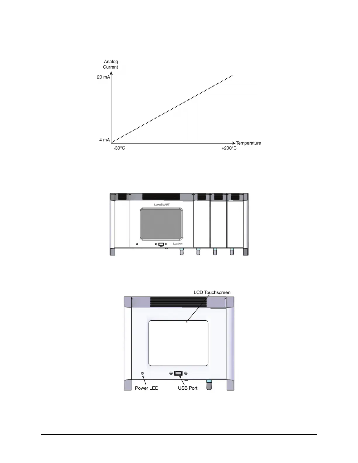
All channels convert a -30 to +200 °C temperature range to a 4 to 20 mA current range, where 4 mA corresponds
to -30 °C and 20 mA corresponds to +200 °C.
Analog Driver Output (Temperature versus Current)
Front Features
Under normal operating conditions, the LumaSMART controller case never needs to be opened. The front panel
displays the temperatures being monitored, relay activation status, and system status.
LumaSMART Controller Front View
The figure below illustrates the components accessible from the LumaSMART controller’s front panel. Table 1
describes the function of each front panel component.
LumaSMART Controller Front View Components

 Loading...