LumaSMART
®
User Manual Introduction • 17
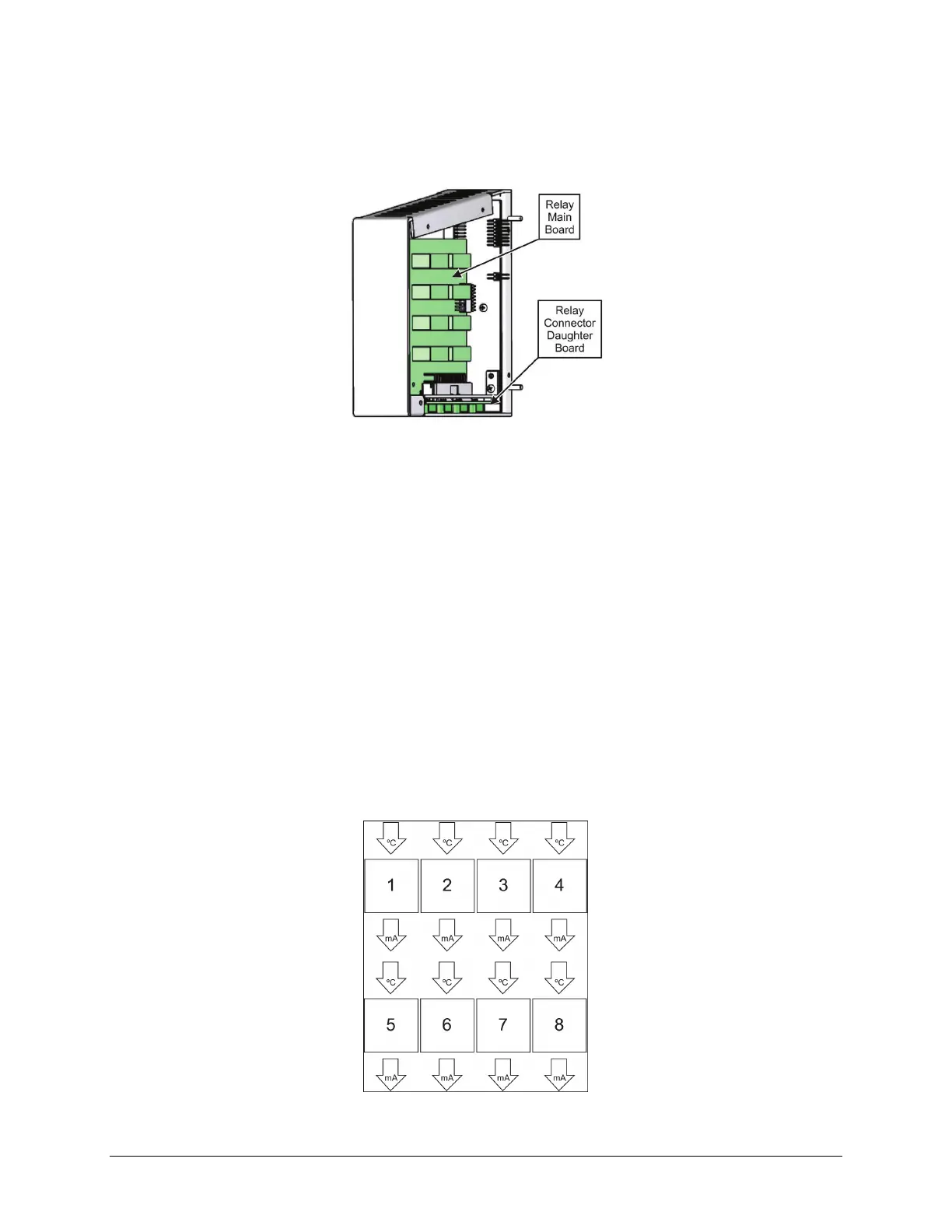
Relay Module
The relay module has eight Form-C relays on its main board. It has the external connectors for the eight relays on a
daughter board.
Relay Module (Internal Components)
Interconnect Board
The interconnect board provides the electrical interconnection between the extra module and the base unit. It also
provides the external connections for power and communications.
Analog Output
The LumaSMART controller has an analog output for each temperature channel on the external connectors for
each FOT module.
Each analog output is associated with a corresponding measurement channel (temperature probes). Analog
outputs are labeled 1 to 16, where Analog Output 1 is associated with Channel 1; Analog Output 2 is associated
with Channel 2, and so forth.
The analog outputs are designed with current drivers that produce a minimum output of 4 mA and maximum
output of 20 mA during normal operation, or alternatively, 0 to 1 mA. During Probe Error and Measurement
generation failure, analog output is a 20 mA.
The analog drivers convert the selected temperature range of each temperature channel to a specified current
range. That is, the analog drivers can be thought of as four blocks with a single input and single output each. The
input of each block is its temperature channel measurement in degrees Celsius (°C) and the output of each block is
a current value (milliamps).
Analog Driver Blocks

 Loading...