LumaSMART
®
User Manual Introduction • 20
LumaSMART Module Back View Mounting
Bottom Features
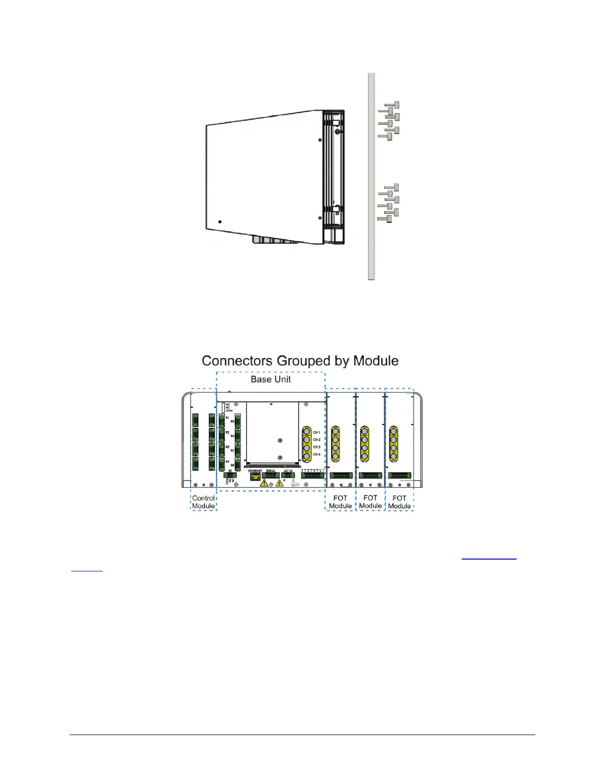
Connections are made to the bottom of the LumaSMART unit. Since the LumaSMART controller can be configured
with multiple modules, the connections are grouped by module.
LumaSMART Controller with FOT and Relay Modules Bottom View
(Front Facing Upwards)
The number of connections a user will need to make will depend on the unit’s configuration (See
Configuration
Options later on in this section for more information on configuration options).
Each module’s connections are discussed below.
Base Unit FOT Connections
The Base Unit can house two or four FOT channels. Each FOT channel has an analog output connector that can be
ordered in the 0-1mA or 4-20mA configuration. The following shows the location and pin-out of these FOT
connections.

 Loading...