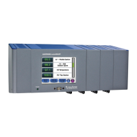
LumaSMART
®
User Manual Introduction • 26
Configuration Options
Table 3: LumaSMART Controller Configuration Options
Component Configuration
Temperature Channels 2 to 16 (in increments of 2)
Analog Outputs (0-1 mA or 4-20 mA) 2 to 16 (1 for each temperature channel)
Relays
System Status
0, 8, 16 programmable, general purpose control
Communications Hardware RS232C, RS485, and Ethernet
Communications Protocols
IEC 61850
DNP3.0
ASCII
Modbus RTU
2.3.2 Probes
LumaSense has developed proprietary, simple-to-use temperature sensing probes, tank wall penetrators,
mounting plates, extensions, and protective NEMA enclosures. The fiber optic probes and extensions are
reinforced to virtually eliminate fiber breakage, thereby reducing associated installation costs.
Probe Design
LumaSense DipTip Rugged Probe and Quality Probe probes are highly flexible, resistant to tensile and compression
forces, and made with Viton® O-ring seals at the transformer tank wall interface. Manufactured with all-silica 0.2
mm (0.008 in) diameter fiber, these probes can be bent around a radius of less than 10 mm (0.4 in) without
breaking.
Probes used with the LumaSMART controller are available in several standard lengths and can be specially ordered
to fit various transformer designs and sizes. The probe sensing tip can be taped directly to the winding conductor
or mounted in radial spacers between conductors.
The probe is run from the sensing point to the internal side of a tank wall penetrator. This oil-tight penetrator is
designed into a 13 mm (0.5 in) National Pipe Thread (NPT) fitting, which can be installed using an appropriately
threaded hole from outside the tank.
A Tank Wall Plate (TWP) assembly is also available from LumaSense, and its carbon steel ring can be welded onto
the transformer wall. The TWP assembly consists of a stainless steel feed-through plate, containing 4 to 24 welded-
on tank wall penetrators, bolted to a carbon steel mounting ring. A Viton O-ring seals the interface between the
stainless steel plate and the carbon steel ring.
(The figure in Section 3.6 provides further details regarding the TWP assembly design.)
Other
Programmable Relay Control Alarm/Restore Temperature set points. Single/Multiple sensor
input
Averaging/Or’ing of Multiple Temperatures
Dimensions Dependent on configuration

 Loading...