LumaSMART
®
User Manual DNP3 Protocol Testing • 122
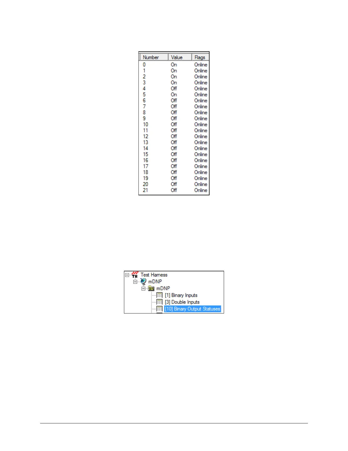
The information in the data window will display the associated values:
Reference the DNP3 mapping at the end of the section. The information includes:
• Numbers 0 ⇒ 4 are system configuration associated with the capabilities of the LumaSMART model.
• Number 5 is the System Status Relay state. On is the default non-alarm state.
• Numbers 6 ⇒ 21 are the states of the Relays 1 ⇒ 16. For systems with fewer than 16 relays, the status
will be shown as Offline.
8.5 Binary Outputs
Select the Binary Output Statuses data in the Data Window

 Loading...