LumaSMART
®
User Manual DNP3 Protocol Testing • 126
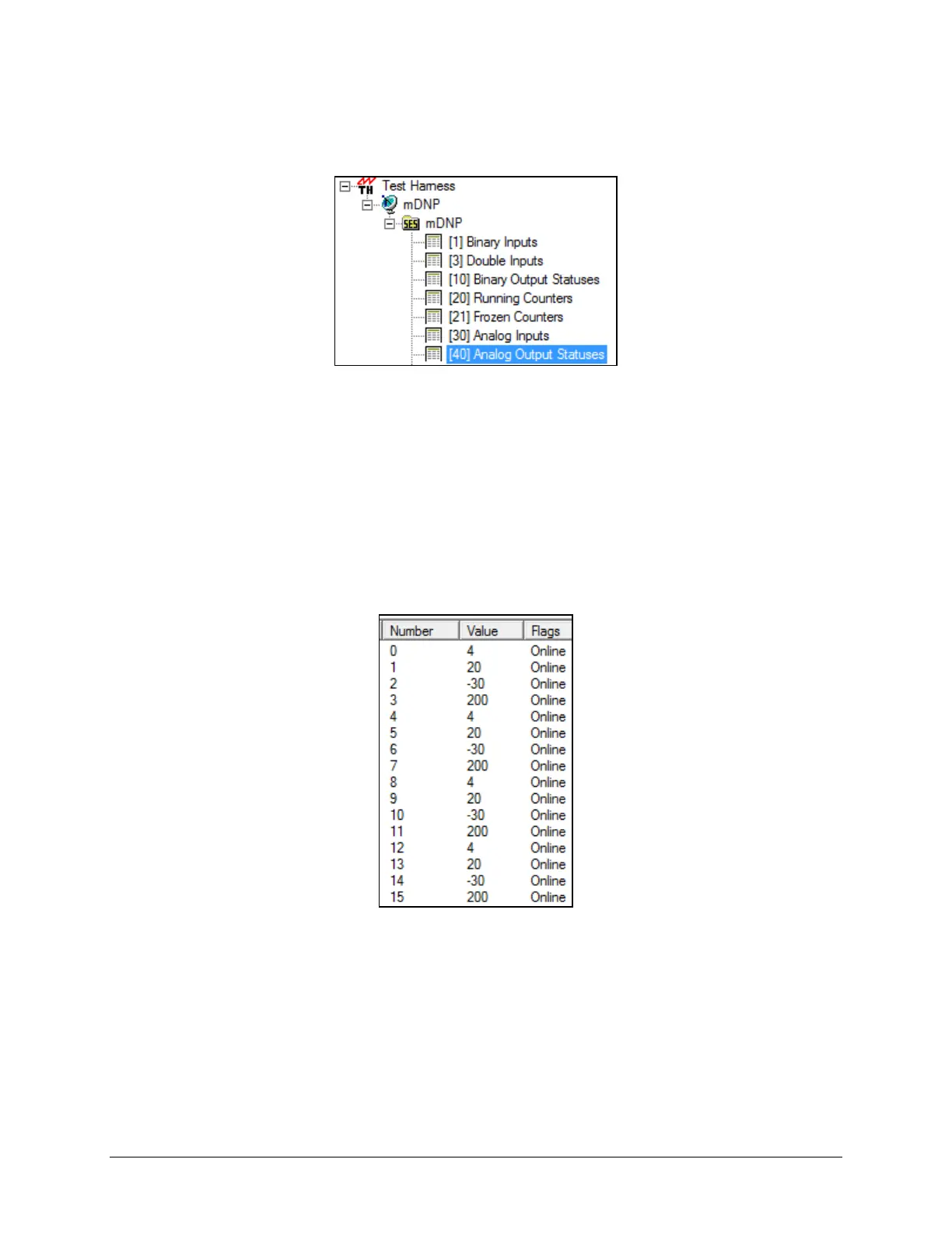
8.7 Analog Output Statuses
To view the analog output statuses, select the Binary Output Statuses data in the data window.
Binary Output Statuses in the data window
The information in the data window will fill with a list of 95 numbers. Reference the DNP3 maps at the end of the
section. The information has 2 main sections:
• Numbers 0 ⇒15 show the analog output values for each of the installed FOT’s.
• Numbers 16 ⇒ 95 show that relay setup parameters for each of the installed Relays.
As showing by example in the following sections, these entries can be modified to control the configuration of the
current loop outputs of the FOT’s and the setup values to the relays.
8.7.1 Configuring FOT Analog Outputs
The following screenshot shows default entries for an analog output:
Default entries for an analog output
The entries are 4 groups of 4 consecutive entries showing each FOT Analog Output Control Values. Reference the
Analog Output section of this manual for more information. The entries for each group, in order, are:
• Minimum Output Current
• Maximum Output Current
• Minimum Temperature representing the Minimum Output Current
• Maximum Temperature representing the Maximum Output Current

 Loading...