LumaSMART
®
User Manual DNP3 Protocol Testing • 125
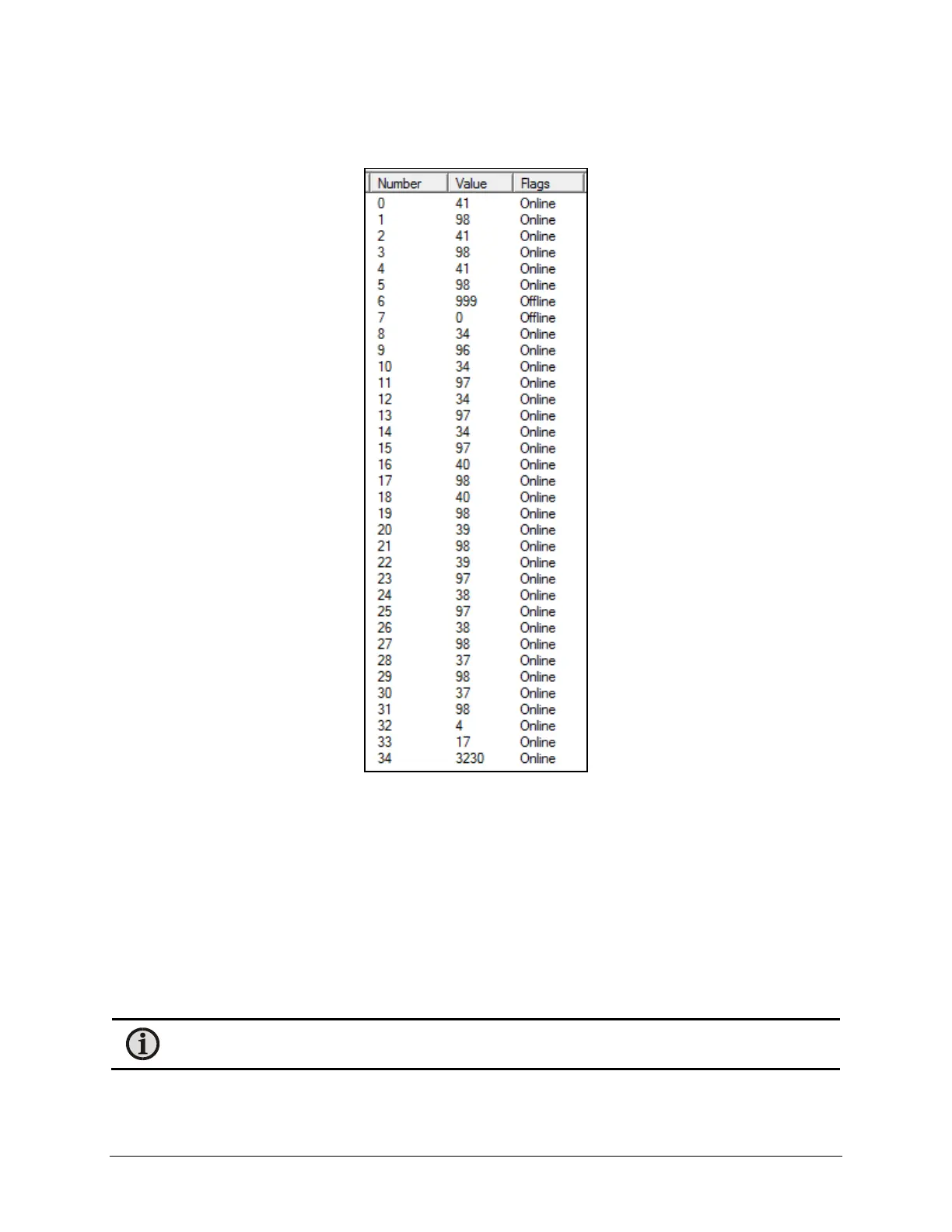
The information in the data window will display the associated values:
Data window
Reference the DNP3 mapping at the end of the section. The information includes:
• Numbers 0 ⇒ 32 are 16 pairs of 2 consecutive entries showing each channels Temperature Reading
followed by the Signal Strength of the same channel.
• Channels that are not installed will show as ‘Offline’
• Number 32 indicates the number of FOT modules installed in the system.
• Number 33 indicates the number of relays in the system. (1 System Status Relay + 16 General Control
Relays)
• Number 34 represents the firmware revision of the LumaSMART. 3230 is version 3.2.3.0
Note: In this example, Channel 4 was disabled and therefore shows 999 as the temperature, 0 as its
Signal Strength, and Flagged as Offline.

 Loading...