LumaSMART
®
User Manual Modbus Protocol Testing • 87
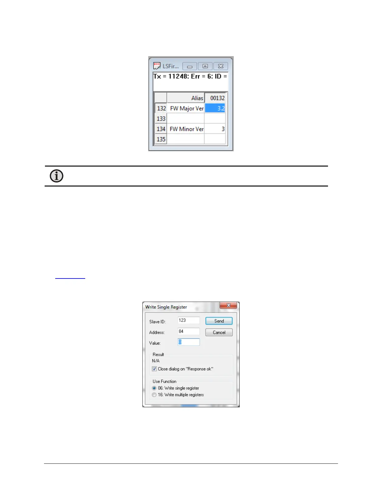
3. The Firmware Version can be read:
Firmware Version
Note: The version number is a 4 digit long, in the form of W.X.Y.Z. However, many Modbus
programs truncate trailing zeros in the displays. So the Version number shown here is 3.2.3.0
6.4 Sample Relay Setup over Modbus
In the following example, Relay 5 will be setup as follows:
1. Enabled – Normally Deenergized
2. Alarm set point set to 35 °C
3. Restore set point to 25 °C
4. Temperature monitoring channels 4 through 6 will drive the relay control.
5. The logic will be set to ‘OR’
See Relay Setup
in Section 5.2.1.4 for more information.
The Modbus Poll program allows the user to access the write function of a holding register by double-clicking on its
value in a specific displayed field. The general format of the edit window that displays is:
Edit Window
In this example, register address 84 was selected, which is Relay 5 Config.

 Loading...