LumaSMART
®
User Manual Installation of the LumaSMART® Controller • 43
4 Installation of the LumaSMART
®
Controller
This chapter describes how to install the LumaSMART
®
controller. It details the wall or panel mounting methods
and provides instructions for wiring the fiber optic extension cables and relays.
LumaSMART installation involves the following:
• A power transformer with manufacturer-installed LumaSense temperature probes;
• Installing the LumaSMART in the external enclosure;
• Connecting fiber optic extension cables between the transformer tank wall penetrator terminals and
LumaSMART probe connectors;
• Connecting the various transformer cooling system actuator controls to the LumaSMART relay
connectors;
• Connecting a power source to the LumaSMART;
Each LumaSMART controller is type tested to meet or exceed the requirements of
IEEE C37.90.1-2002.
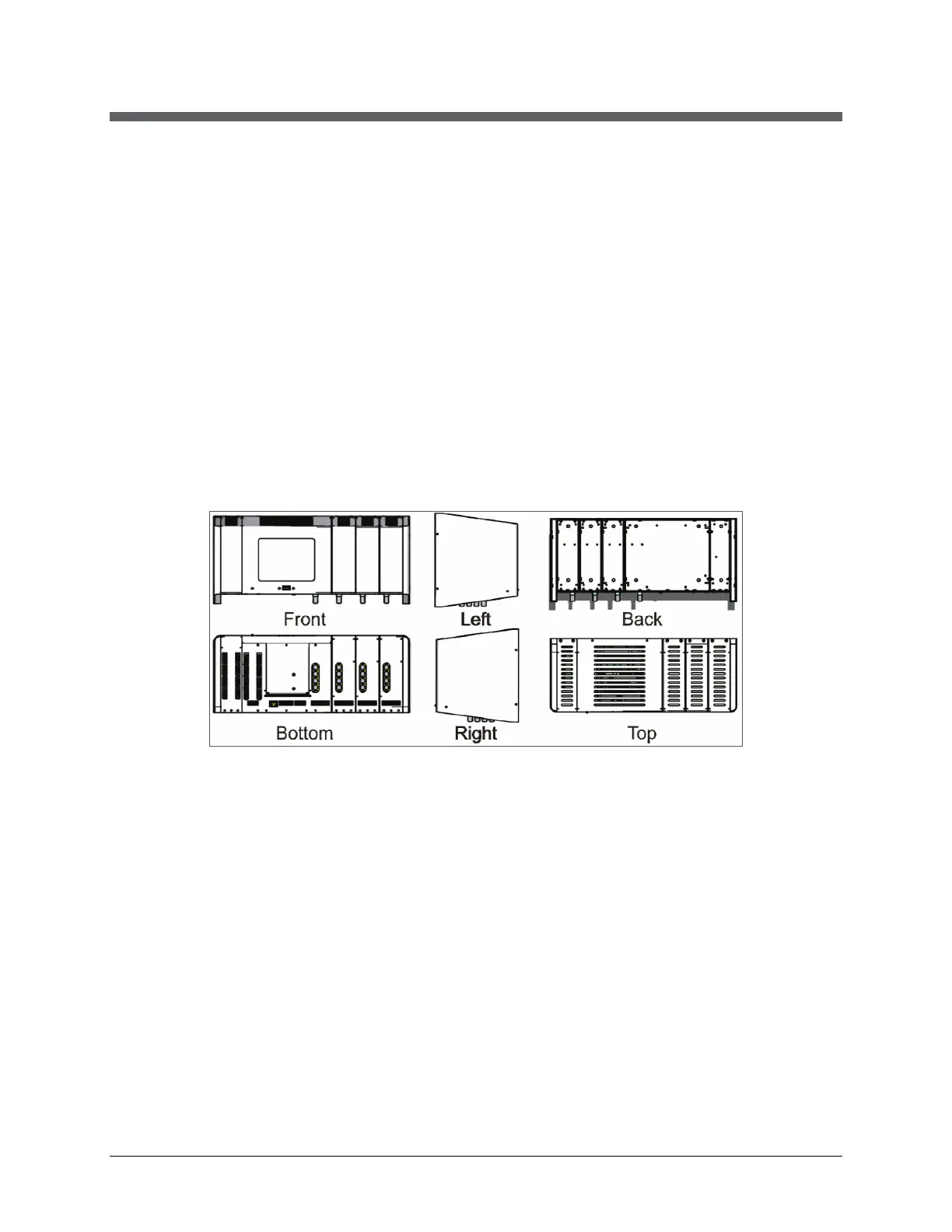
LumaSMART Controller with Added FOT and Relay Modules
Features of the LumaSMART include:
• Can be configured with 4 to 16 channels of Fiber Optic Temperature measurement. Each of the FOT
channels has an analog output.
• Can be configured with 0, 8, or 16 control relays whose trigger points can be set by the user.
• Has a Failsafe configured System Status Relay that is Deenergized (turned off) whenever a system fault is
detected.
• Has an Ethernet port, a RS485/RS232c and a USB port. Communication protocols include ASCII, IEC 61850,
Modbus and DNP 3.0. The USB port can be used to download the data log or to upgrade the LumaSMART
firmware.
• The LumaSMART controller has a universal power supply that accepts 90 to 264 VAC or 127 to 370 VDC,
47 to 63 Hz.

 Loading...