LumaSMART
®
User Manual Introduction • 16
Internal Components
Access to the inside of the LumaSMART controller is rarely needed since all connections to the LumaSMART
controller are made along the exterior surface.
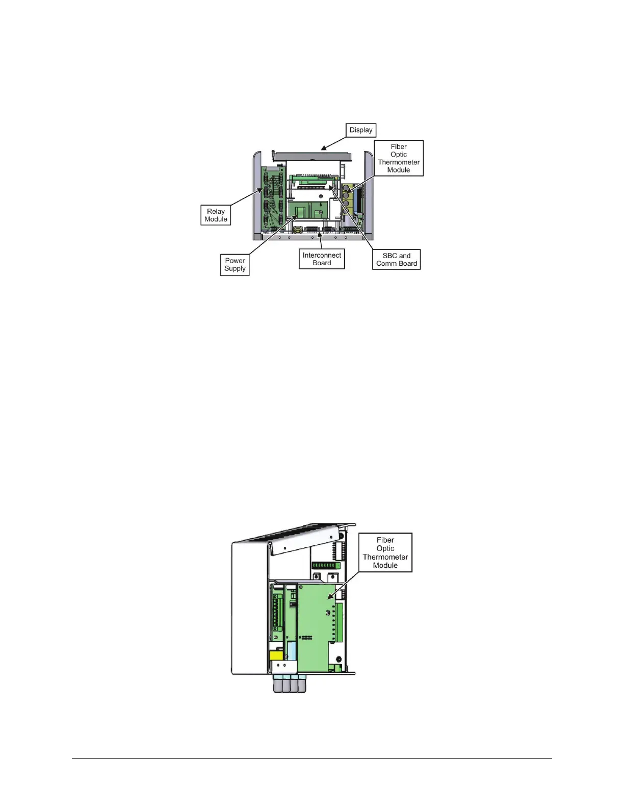
LumaSMART Controller Internal Components (Front Facing Upwards)
Display
The LCD is a VGA TFT display with integrated touch panel which allows both data display and data entry. The
display has an LED backlight with user programmable intensity and time to wait before it dims.
SBC and Comm Board
The SBC is an industrial Windows Embedded PC in a PC104+ form factor. The COMM Boards is a PC104 board that
adds four RS232c ports to the SBC.
Power Supply
The power supply is a universal input power supply capable of operating from 100 to 240 VAC, 50/60 Hz or 127–
370 VDC.
Fiber Optic Thermometer Module
The fiber optic thermometer modules each contain up to four standard optical ST connectors (channels) that
accept connections from the temperature probes through fiber optic extensions cables. The other ends of the
extension cables are connected to the tank wall penetrator terminals.
FOT Module (Internal Components)

 Loading...