LumaSMART
®
User Manual Modbus Protocol Testing • 83
Note: To perform this test using the TCP/IP interface, the Modbus Poll program would need to be
reconfigured to use the TCP/IP interface as well. The results would be the same.
6.3 Testing Modbus Functions
The follow examples demonstrate the basics of monitoring, configuration, and control of the
LumaSMARTcontroller through the Modbus Protocol.
6.3.1 Read Coils (0x01)
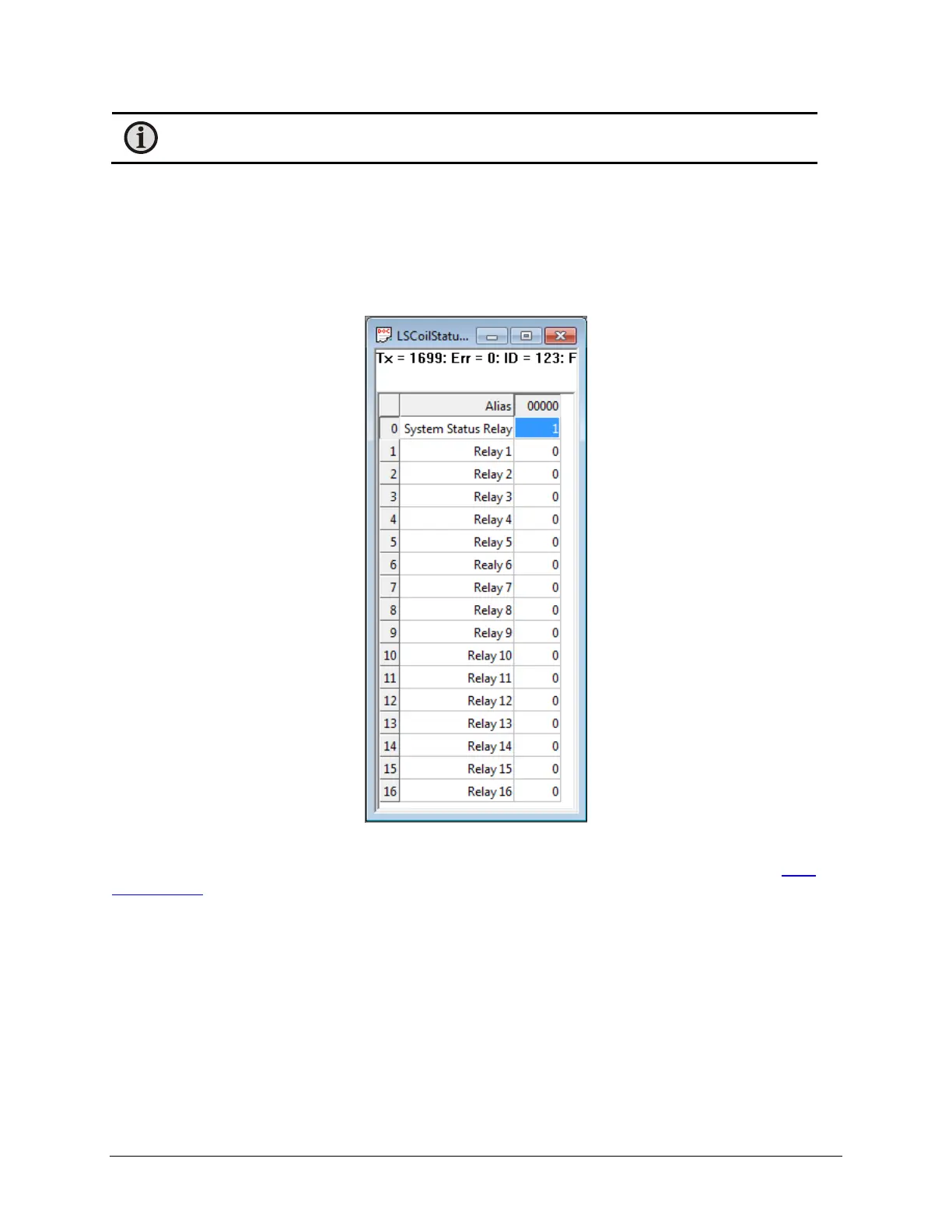
In this example, the coil status is shown as:
Coil Status
A value of 1 indicates that the relay is Energized and a value of 0 indicates Deenergized. See Section 4.3.3
Relay
Output Wiring. As shown above, all relays are Deenergized except the System Status Relay, which Energized when
no system error is occurring.
The coil status is read-only since control of the state is based on the user configuration.

 Loading...