LumaSMART
®
User Manual Modbus Protocol Testing • 88
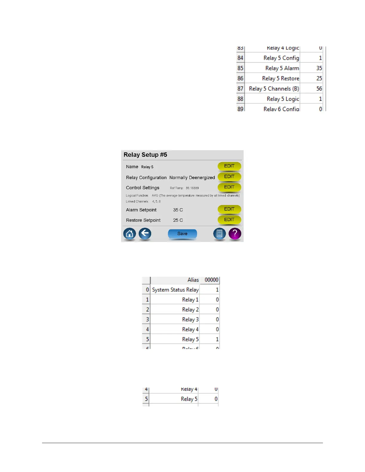
The value was changed to 1 to specify Enabled – Normally Deenergized
Register Address 85 was set to 35 (Alarm Setpoint)
Register Address 86 was set to 25 (Restore Setpoint)
Register Address 87 was set to (0000 0000 0011 1000 binary) = 56 Decimal =
only bits for channels 4, 5 and 6 were set.
Register Address 88 was set to 2 to specify ‘OR’ logic.
Additionally, the read holding register address 148 was read to ensure that
the bits for channels 4, 5, and 6 were set (make sure that the associated
input probe channels are enabled).
Checking the registers for Relay 5 shows that the desired values are stored.
You can also verify by reviewing the LumaSMART relay setup screen:
Relay Setup screen
Given the Ref Temp of 36+ °C, the relay should Energize.
Reviewing of the Modbus Coil Status also confirms that, under this condition, the relay did Energize.
Coil Status
Setting the value of register 84 to 2 – Normally Energized will cause the ‘config’ of the relay to change from
‘Normally Deenergized’ to Normally ‘Energized'. The result is reflected in the Coil Status showing the relay is now
Deenergized.
Coil Status Deenergized

 Loading...