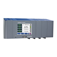
LumaSMART
®
User Manual Introduction • 25
Connections Relays: Phoenix
Analog Output: Phoenix
Serial: Phoenix
Ethernet: RJ45
Power: Phoenix
Caution: Make sure to check the ID label on the LumaSmart unit to confirm that the input voltage
Serial Interface
Front Panel USB Port Status and Data Log Downloading
Firmware Updating
Communication RS232C
RS485
Ethernet
Protocols: ASCII, IEC 61850, Modbus RTU, DNP3.0
Analog Outputs
Analog Outputs
4 to 20 mA or 0 to 1 mA
Phoenix connectors
Relay Outputs
Number of Relays 0, 8, 16
Relay Type(s) Eight Form-C relays (one board)
Phoenix connector
Input Voltage 5 A @ 30 VDC or 8 A @ 250 VAC (max)
System Fault Relay One separate, dedicated Relay with Separate Terminals
System Fault Conditions Fixed: See Section 4.3.3.1 System Status Relay
Surge Protection
Surge Protections 4,000V (IEEE C37.90.1-2002)
Memory
Memory 4 GB of data storage. Capture rate fixed at 1 minute intervals on all
temperature readings, error codes and relay statuses. Retains
more than 40 years of data.
Can be cleared by Administrator command
Date/time stamped

 Loading...