CSP−900RMM−2MD Helicopters, Inc.
Rotorcraft Maintenance Manual
Page 219
Revision 35
06-00-00
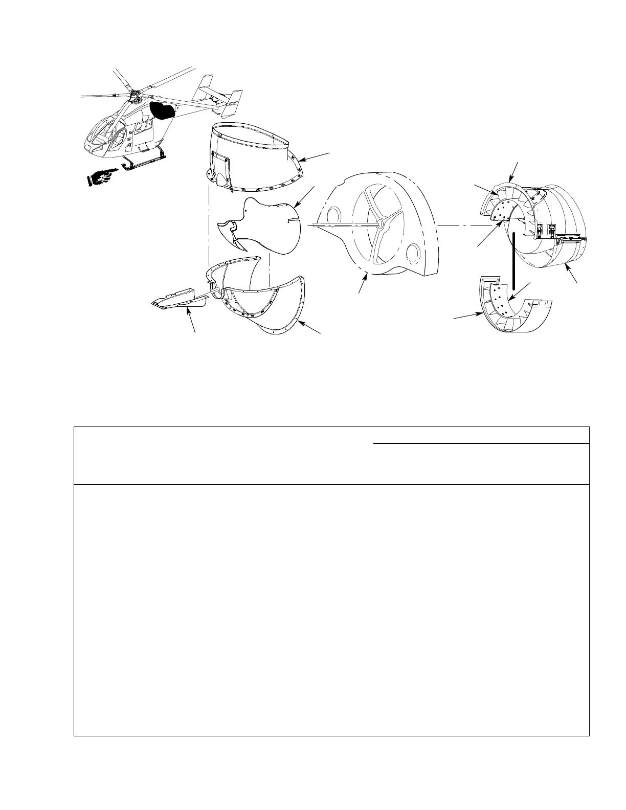
REF. STATOR
9G06-013A
REF. FAN SUPPORT AND
HOUSING
F1
F2
F3
F4
F5
F6
F7
F9
F8
Figure 213. Fan Assembly Access Panels
Legend (Ref. Figure 213)
Item
No.
Name Permits Access To
Removal and Installation
Quantity Type
Method
Ref.
Figure 204
F1 Anti−Torque Drive
Shaft Cover
Fan Drive Shaft 6 Screw L
F2 Anti−Torque Lower
Inlet Duct Assembly
Plenum Fan Assembly 19
14
Screw
Bolt
L
M
F3 Anti−Torque Fan
Fairing/Center Body
Assembly
Fan Assembly, Fan Driveshaft
Coupling, Support Housing,
Fan Balance Monitor System
Magnetic Pickup and
Accelerometer
19 Screw L
F4 Anti−Torque Middle
Inlet Duct Assembly
Fan Assembly Plenum Air Inlet 4
19
Screw
Bolt
L
M
F5 Anti−Torque Fan
Upper Duct Assembly
Plenum Air Inlet, Upper Stator
Blades Attached
24 Screw L
F6 Upper Center Diffuser Upper Stator Blades Attached 24 Screw L
F7 Lower Center Diffuser Fan Assembly and Diverter,
Lower Stator Blades Attached
20 Screw L
 Loading...


