CSP−900RMM−2MD Helicopters, Inc.
Rotorcraft Maintenance Manual
Page 447
Original
28-00-00
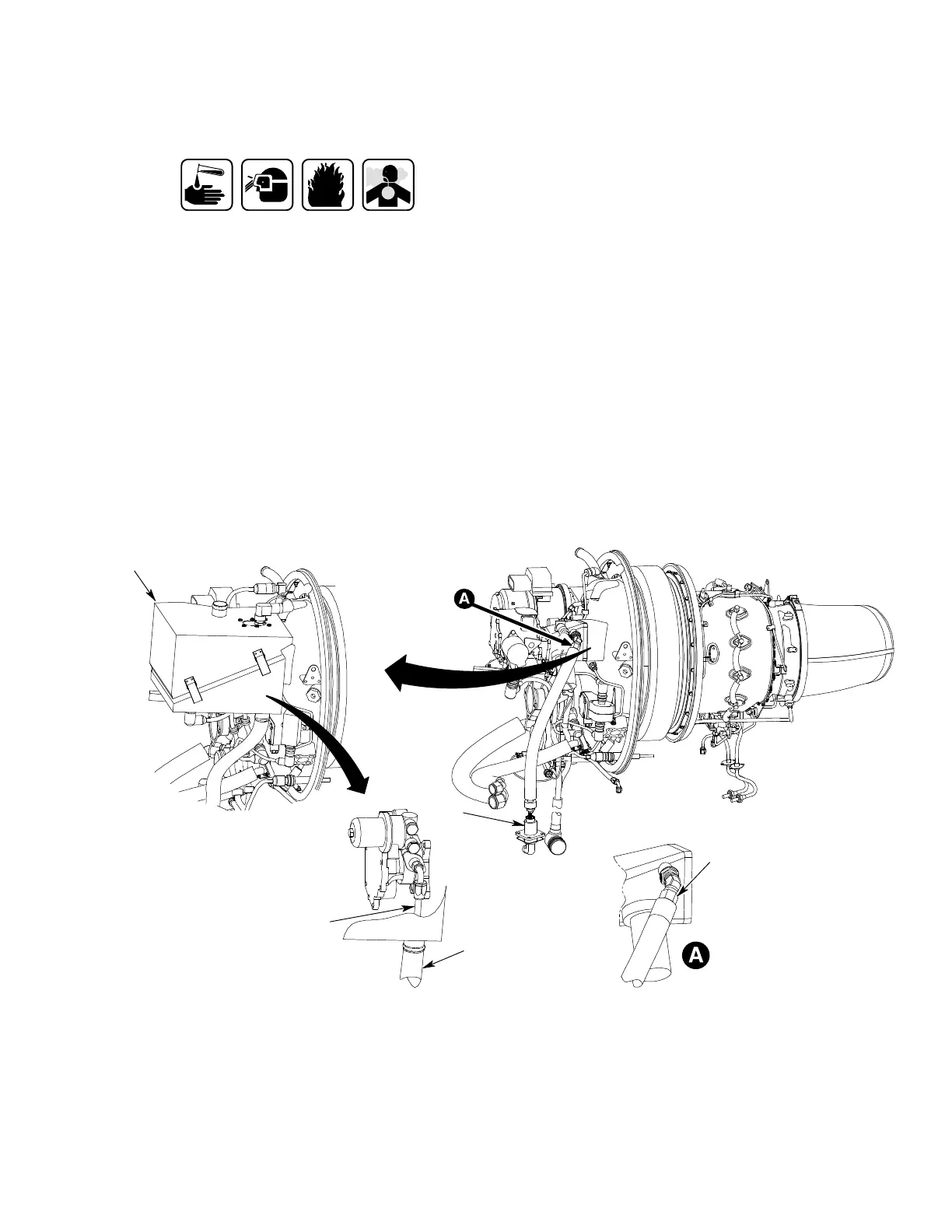
(a). Install spacers on fuel feed hose (3)
Sealing Compound (C207)
(b). Apply a fillet of sealing compound
(C207) at junction of spacer and hose.
Ensure that sealing compound does
not block holes in spacer.
(c). Install vapor shroud hose (4) over
fuel feed hose and spacers.
(d). Connect upper end of fuel feed hose
to engine driven fuel pump elbow
fitting. Torque fuel feed hose nut.
(e). Connect lower end of fuel feed hose to
frangible valve fitting. Torque fuel
feed hose nut and safety with lock
wire (C702).
(f). Perform fuel booster pump operation
al test (Ref. Section 28-00-00) and
check for fuel leakage.
(g). Connect vapor shroud hose and
secure with lockwire (C702).
(h). Close FMU vapor shroud box (5).
(i). Install screws attaching FMU fuel
shroud box to FMU connector.
(j). Connect vapor shroud duct to top of
FMU vapor shroud box. Secure vapor
shroud duct with lockwire (C702).
(k). Perform fuel supply vapor shroud
leak check/pressure test (Ref. Section
28-00-00).
(l). Install aft swashplate fairing assem
bly (Ref. Section 53-30-00).
(m). Close upper and lower transmission
access door assembly L210 or R210
(Ref. Section 06-00-00).
1
2
9G28-044A
LEFT ENGINE
LOOKING INBOARD
902 CONFIG
4
902 CONFIG
5
3
1. ENGINE FUEL FEED HOSE ASSEMBLY (900 CONFIG)
2. ENGINE DECK FRANGIBLE VALVE
3. ENGINE FUEL FEED HOSE ASSEMBLY (902 CONFIG)
4. ENGINE FUEL FEED VAPOR SHROUD HOSE (902
CONFIG)
5. FMU FUEL SHROUD BOX (902 CONFIG)
Figure 418. Engine Fuel Feed Hose