F
THE GEARBOX
\xxxw.‘
Fig.
F.3
Laygear
assemblyisecond
type
1.
Thrust
Washerismall.
4.
Laygear.
2.
Needle-roller
bearing (pair).
5.
Layshaft.
3. Distance
tube
6.
Thrust washerilarge.
Section F.5
DISMANTLING AND
ASSEMBLING
THE FIRST
MOTION SHAFT
1.
Remove
the
spindle rollers
from the
spigot
bearing
housing.
2.
Secure
the
shaft
in
a
soft-jawed
vice,
release
the lock
washer, and,
using
Service
tool 18G 5,
unscrew
the
locknut.
NOTE.~The
locknut has
a
left-hand thread.
3.
Press
the bearing
from the
shaft and
remove
the
spring
ring
from the bearing.
Assembly
is
a
reversal
of
the
dismantling
sequence.
Section F.6
DISMANTLING
AND
ASSEMBLING
THE
LAYGEAR
FIRST
TYPE
Remove
the
circlips
from the ends
of
the laygear
and
withdraw
the
needle-roller bearing
assemblies
and the
distance
tube.
To
assemble the laygear
proceed
as
follows:
1.
Hold
the
layshaft
in
a
vice,
stepped end
downwards.
2. Smear
the shaft with
grease
and
assemble
a
bearing
assembly,
the distance
tube, and the remaining
two
bearing
assemblies
to
the
shaft.
3.
Fit
a
circlip
to
the
front end
of the laygear and
place
the laygear
on
the
shaft.
4. Remove
the laygear
and
shaft from the
vice,
fit
the
remaining
circlip, and
remove
the
shaft from the
gear.
SECOND
TYPE
The
second-type laygear
has
a
larger diameter
shaft
and
a
pair
of caged
needle-roller
bearings
at
each end.
Extract
the
two
pairs
of
needle-roller bearings
from the
ends of the laygear
and the distance tube
from the
small
end.
To
assemble
the laygear
proceed
as
follows:
1.
Dip
the bearings
in
oil.
2.
Hold
the
laygear
in
a
vice
and
insert
the distance
tube
and
a
pair
of
bearings
at
the small end.
3. Insert
a
pair
of bearings
at
the
large
end.
F.6
Section F.7
DISMANTLING THE THIRD MOTION SHAFT
Before
dismantling the third
motion
shaft
check the
end-■oat
on
the third speed mainshaft
gear
to
ensure
the
fitting of the
correct
thrust washer during reassembly of the
third
motion
shaft.
1.
Remove
the third and
fourth
speed
gear
front
baulk
ring,
the synchromesh sleeve
and hub, and the
rear
baulk
ring.
The synchromesh sleeve
may
be
withdrawn
from the hub, but
care
must
be taken
to
retain
the
balls and
springs
that will be released when the sleeve
is
withdrawn from the hub.
2. Depress
the
front
thrust
washer
retaining
peg,
rotate
the washer
to
align
its
splines with those
on
the shaft,
and
remove
the washer.
3.
Withdraw the third speed
gear
and
its
bush and
then
remove
the
bush interlock
ring
to
free
the second
speed
gear.
Remove
the
gear,
baulk
ring,
bush,
and
thrust washer.
4.
Withdraw the ■rst and
second
speed synchromesh
and
gear.
The
■rst
gear may
be disengaged
from
the hub,
but
care
must
be taken
to
retain
the balls and
springs
that
will be released when the
gear
is
withdrawn from
the hub.
5. Remove
the speedometer drive
gear
and
its
Woodruff
key and then slide
the distance
piece
from
the
shaft.
6. Press
the
bearing
from the shaft
and
then from
its
housing.
Section F.8
EXAMINATION OF COMPONENTS
Thoroughly clean, dry, and
examine
all
components
for
wear,
distortion, deterioration, and
thread damage,
paying
particular
attention
to
the following:
1.
Bushes fitted
to
the
clutch withdrawal fork,
third
motio‘n
shaft,
and
reverse
speed
gear.
Worn
or
damaged
bushes should
be renewed
(Section
F.1
1).
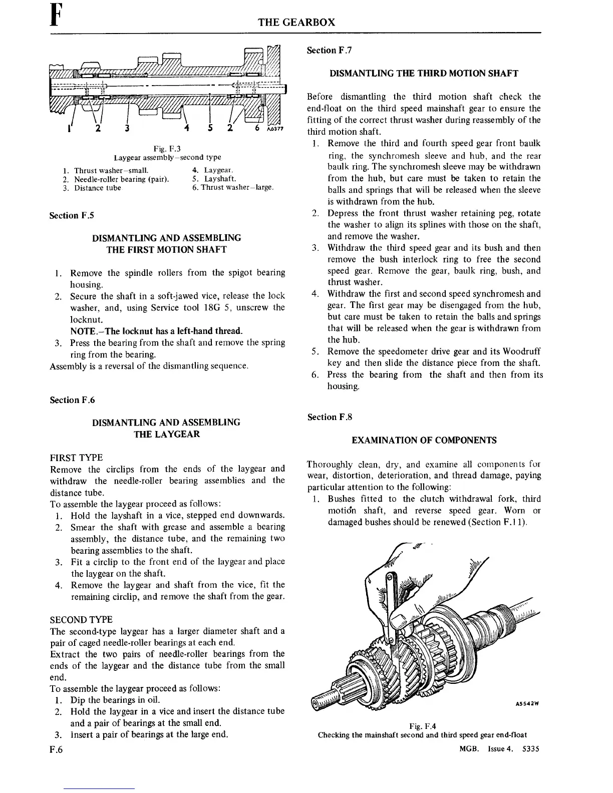
A5542W
Fig.
F.4
Checking the mainshaft
secondand
third speed
gear
end-float
MGB.
Issue4.
5335