A
THE
ENGINE
“
\
lIHllllHllllllllllllllllll
“Ill
5
m
utm/I/m/
g
:::::::::mun
ML/
Fig. A.29
The distributor
drive with the
slot
in the
correct
position and
the large
offset
uppermost
Section A.25
DISTRIBUTOR DRIVING
SPINDLE
(18G/18GA)
Removing
Remove
the distributor
as
detailed
in Section B.
Take
out
the
screw
securing
the distributor housing
to
the
cylinder block and withdraw
the housing.
Screw
a
'158‘i11.
UNF.
bolt approximately 3%
in.
(89 mm.)
long
into
the threaded
end
of the distributor drive spindle
and withdraw the spindle.
Re■tting
Turn
the crankshaft until No.
1 piston is
at
T.D.C.
on
its
compression
stroke. When the
valves
on
No.
4
cylinder
are
‘rocking’
(i.e.
exhaust
just
closing and inlet
just
opening)
No.
1 piston
is
at
the
top
of
its
compression
stroke. 1f the
engine is
set
so
that the
groove
in
the crankshaft
pulley
is in
line with the
largest
pointer
on
the
timing
chain
cover, or
the dimples
in
the crankshaft and camshaft
gears are
in
line,
the
piston is
exactly
at
T.D.C.
Screw
the
%
in.
by 3%
in.
UNF. bolt
into
the threaded
end
of
the distributor
drive
gear
and,
holding
the
drive
gear
with
the slot
just below
the
horizontal and the
large
offset
uppermost, enter
the
gear.
As
the
gear engages
with the
camshaft
the slot
will
turn
in
an
anti-clockwise
direction
until
it
is
approximately
in
the
two
o’clock
position.
Remove the bolt from
the
gear,
insert
the
distributor
housing,
and
secure
it
with the special bolt
and washer.
Ensure
that the
correct
bolt
is
used
and
that the
head does
not
protrude above the
face of the housing.
Re■t
the
distributor, referring
to
Section B.5
if
the clamp
plate has
been
released.
3
A.28
Section
A.26
DISTRIBUTOR
DRIVING SPINDLE
(180B)
Removing
Remove the distributor
as
detailed
in Section B.
Take
out
the
screw
securing
the distributor
housing
to
the
cvlinder
block
and withdraw the housing.
Screw
a
%
in.
UNF. bolt
approximately 31/;
in.
(89 mm.)
long
into
the threaded
end of the distributor
drive spindle
and with the
crankshaft
at
90°
or
A.T.D.C.
(pistons
halfway
up
the bores)
withdraw
the spindle.
Refitting
Screw
the
T'Sg'
in.
UNF. bolt
into
the threaded
end
of
the
distributor
drive
spindle and with the
crankshaft
in
the
90°
B.
or
A.T.D.C.
position,
enter
the spindle.
Turn the crankshaft
until
N0.
1 piston is
at
T.D.C.
on
its
compression
stroke. When the valves
on
No.
4
cylinder
are
‘rocking’
(i.e.
exhaust
just
closing
and inlet
just
opening)
No.
1 piston is
at
the
top
of
its
compression
stroke.
If
the
W.
\\\\\\\\
\\
/
In“
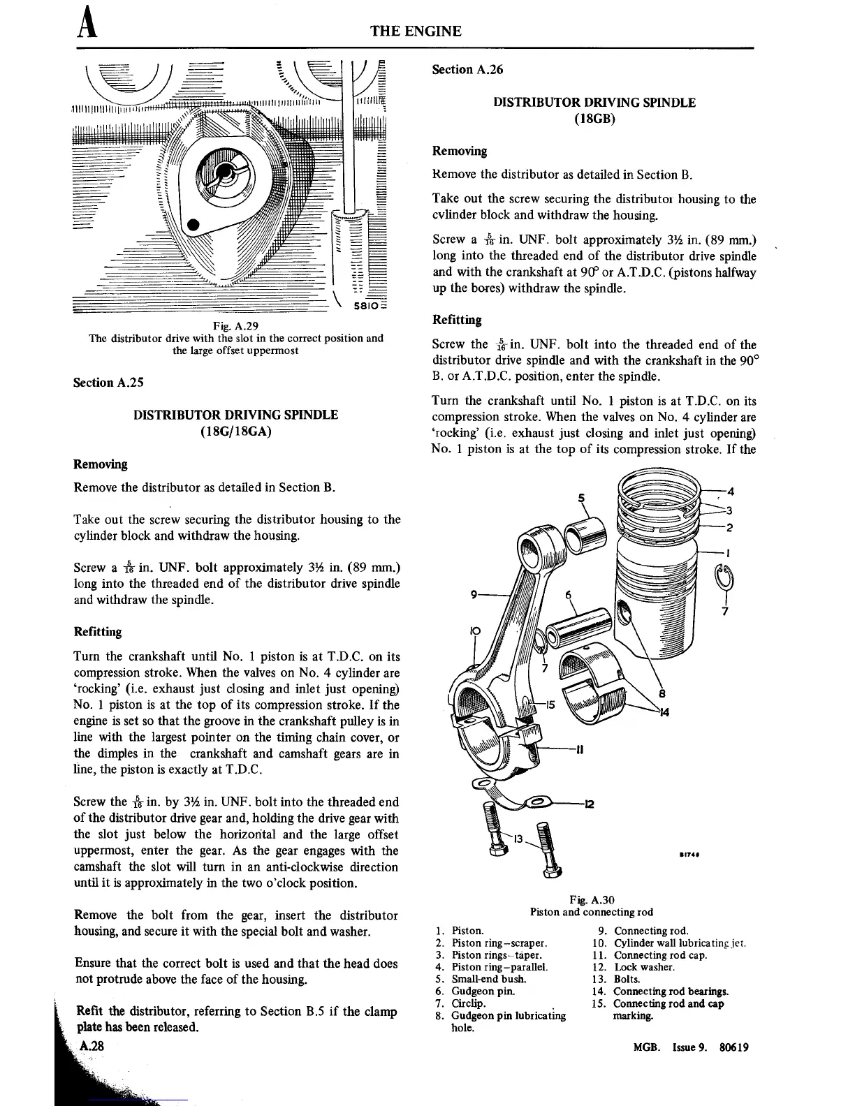
Fig.
A.30
Piston and
connecting rod
1.
Piston.
9.
Connectingrod.
2. Piston ring—scraper. 10. Cylinder wall lubricating jet.
3. Piston rings~taper.
ll.
Connectingrod
cap.
4. Piston ring—parallel. 12. Lock washer.
5.
Small~endbush.
l3. Bolts.
6.
Gudgeon
pin. 14.
Connecting
rod
bearings.
7.
Circlip.
,
15. Connecting
rod and
cap
8.
Gudgeon
pin lubricating marking.
hole.
MGB.
Issue
9. 80619