B
THE BODY
Section
R]
FRONT GRILLE
Removing
Unscrew
the
three
screws
securing
the steady brackets.
Remove the
three
hexagon-headed
screws
securing
the
bottom
of
the
grille.
Remove
the
motif, steady brackets,
and the rubber
buffers.
GHNS
and
GHDS
cars
1.
Remove
the three
screws
in
the bonnet
lock
platform,
and the
two
self-tapping
screws
securing
the
grille
outer
surround
to
the body.
2.
Prise
out
the three
rubber body plugs and
remove
the
three
screws
securing
the bottom
of the grille
to
the
radiator
duct panel.
Section R.2
BONNET AND BONNET
LOCK
I
Removing
The
bonnet
is
of
light-alloy material.
Mark the hinges,
support
it in
the
open
position
and
remove
the
two
nuts,
washers, and
screws
that
secure
each hinge
to
the bonnet.
Disengage the
stay
and
lift the
bonnet
from the
car.
Slacken
the
nut
from the bonnet lock
pin
and withdraw the
pin,
thimble, and
spring.
Remove
the three
screws
securing
the
safety
catch
to
the bonnet and detach the
safety catch.
From
the bonnet
lock platform
remove
the
two
screws
securing
the
safety
catch bracket and
take off
the bracket.
‘
Release the bonnet
lock control cable clamp
screw
and
pull
the cable from the bonnet lock
plate.
Unscrew the three
screws
securing
the locating
cup
and
bonnet
lock
to
the
platform and
remove
the
cup
and lock.
Refitting
Refitting
is
a
reversal
of
the removal
sequence,
but
ensure
that the
bonnet
lock,
safety
catch, and the bonnet
are
correctly aligned
before finally
tightening the
securing
screws.
After
assembly adjust the latch
pin
to
obtain
ease
of
closing, lubricate the lock, catch, hinges and check them for
correct
operation.
I
A909SW
Fig.
R.1
A section through
a
windscreenpillar, showing:
1. Glazing rubber. 4. Rivet~seal retainer.
2.
Bottom
reinforcement.
5. Sealretainer.
3.
Screw—reinforcement
to
6. Seal.
pillar.
R.2
r‘
_;
\
\
\3
>1.-
»1,
4
4;-
“V
\
\
9:3
5
AS
502W
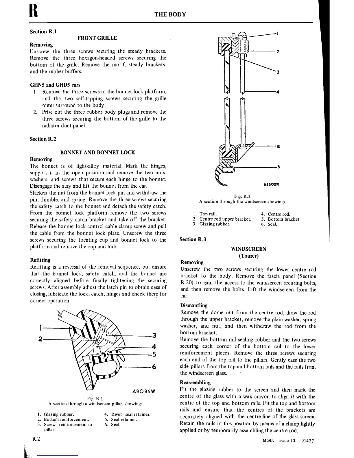
Fig. R.2
A section through the
windscreenshowing:
4.
Centre rod.
5. Bottom bracket.
6. Seal.
.
Top rail.
.
Centre
rod
upper
bracket.
.
Glazing
rubber.
th—t
Section
R.3
WINDSCREEN
(Tourer)
Removing
Unscrew
the
two
screws
securing
the
lower
centre
rod
bracket
to
the body.
Remove
the fascia
panel
(Section
R20)
to
gain
the
access
to
the
windscreen
securing
bolts,
and
then
remove
the bolts.
Lift the
windscreen from
the
car.
Dismantling
Remove
the
dome
nut
from
the
centre
rod,
draw the rod
through
the
upper
bracket,
remove
the
plain
washer,
spring
washer,
and
nut,
and then withdraw
the
rod
from the
bottom
bracket.
Remove the bottom
rail
sealing rubber
and
the
two
screws
securing
each
corner
of
the bottom
rail
to
the
lower
reinforcement
pieces.
Remove the three
screws
securing
each
end
of
the
top
rail
to
the
pillars. Gently
ease
the
two
side
pillars
from
the
top
and bottom
rails and the
rails
from
the windscreen
glass.
Reassembling
Fit the
glazing
rubber
to
the
screen
and then mark the
centre
of
the
glass
with
a wax crayon
to
align
it
with the
centre
of
the
top
and bottom
rails. Fit the
top
and
bottom
rails and
ensure
that the
centres
of
the brackets
are
.accurately
aligned
with the
centre-line
of the
glass
screen
Retain the
rails
in
this
position
'by
means
of
a
clamp lightly
applied
or
by
temporarily assembling
the
centre
rod.
MGB.
Issue
10.
91427