THE
ENGINE
Lubricate
the
main
bearing cap
joint seal
liberally
with oil
before
re■tting. When re■tting the bearing
caps
on
early
engines
use a
new
locking plate
to
lock the
nuts;
on
later
engines
check
that the self-locking
nuts
lock
to
the stud
threads ef■ciently. Tighten the bearing
cap
nuts to
the
torque
■gure
given
in
‘GENERAL
DATA’.
Section
A.14
PISTONS AND
CONNECTING
RODS
Remove
the cylinder
head
as
in
Section
A.6. Drain
and
remove
the
sump
and
oil strainer
as
in
Section
A.1
l.
The
pistons
and
connecting
rods
must
be
withdrawn
from
the
top
of the
cylinder block.
Unlock and
remove
the
big-end
bolts
and
remove
the
bearing
caps.
Release
the
connecting
rod
from the
crankshaft.
Withdraw the
piston
and
connecting
rod from the
top
of
the cylinder
block and
refit the
bearing
cap.
The big-end
bearing
caps are
offset. When
used
parts
are
replaced after
dismantling
it is
essential
that they should
be
■tted
in
their
original
positions.
In
order
to
ensure
this, mark the
caps
and
connecting
rods
on
their sides which
are
■tted together
with the number of the cylinder from
which each
was
taken.
Replacement
of the
piston
and
connecting
rod
is
a
direct
reversal
of the
above,
but the
piston
ring
gaps
should
be
set
at
90°‘to
each other.
It
is
essential
that the
connecting
rod and
piston
assemblies
should be
replaced
in
their
own
bores and
■tted
the
same
way
round,
i.e.
with the
gudgeon
pin
clamp
screw on
the
camshaft
side
of the
engine.
The
piston
crowns are
marked
‘FRONT’
to
assist
correct
assembly
to
the
connecting
rods.
Re■t the big-end
bearings
in
their original
positions.
Pistons
and
gudgeon
pins
(18G/18GA)
The gudgeon
pin is
rigidly held
in
the split little-end
of
the
connecting
rod by
a
clamp bolt
engaging
the central
groove
of
the gudgeon
pin.
AD1381
Fig.
A.19
Assembly positions of the connecting rods, showing the offsets
1329MGB.
Issue
4.
%<
i
’47/l/
/
//’///////
/////
4%
A5060A‘
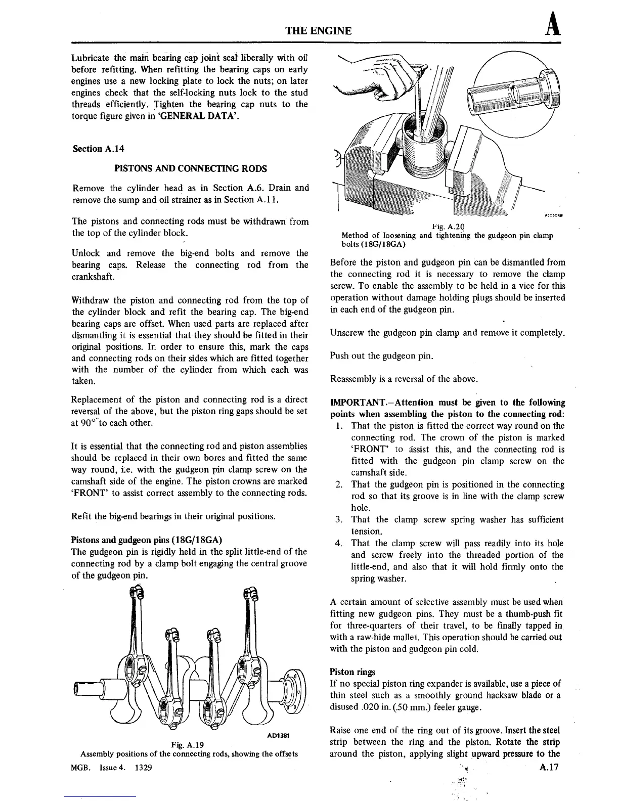
Fig.
A20
Method of loosening and tightening the
gudgeonpin clamp
bolts
(18G/18GA)
.
Before the
piston
and
gudgeon
pin
can
be
dismantled
from
the
connecting
rod
it is
necessary
to
remove
the clamp
screw.
To
enable the assembly
to
be held
in
a
vice
for this
operation
without damage holding plugs should
be inserted
in
each
end
of the gudgeon
pin.
Unscrew the gudgeon
pin
clamp and
remove
it
completely.
Push
out
the gudgeon
pin.
Reassembly
is
a
reversal
of
the above.
IMPORTANT—Attention
must
be given
to
the
following
points when assembling the
piston
to
the
connecting
rod:
1.
That the
piston is
■tted
the
correct
way
round
on
the
connecting
rod. The
crown
of the
piston is
marked
‘FRONT’
to
assist
this,
and the
connecting
rod
is
■tted
with the gudgeon
pin
clamp
screw on
the
camshaft
side.
2.
That
the gudgeon
pin is
positioned
in
the
connecting
rod
so
that
its
groove
is in
line with the
clamp
screw
hole.
3.
That the clamp
screw
spring
washer
has
suf■cient
tension.
4.
That the
clamp
screw
will
pass
readily
into its
hole
and
screw
freely
into
the threaded
portion
of
the
little-end,
and also
that
it
will hold
■rmly
onto
the
spring
washer.
A certain
amount
of
selective assembly
must
be used
when
■tting
new
gudgeon
pins.
They
must
be
a
thumb-push
■t
for three-quarters of their
travel,
to
be
■nally
tapped
in,
with
a
raw-hide mallet.
This
operation
should be carried
out
with the
piston
and gudgeon
pin
cold.
Piston rings
If
no
special
piston
ring
expander
is
available,
use a
piece
of
thin
steel
such
as
a
smoothly ground hacksaw
blade
or a
disused
.020
in.
(.50 mm.) feeler
gauge.
Raise
one
end
of the
ring
out
of
its
groove.
Insert
the
steel
strip
between the
ring
and
the
piston.
Rotate
the
strip
around the
piston,
applying
slight upward
pressure
to
the
"a
'
A.l7
at,
r
*3:
r
y