B
THE
IGNITION SYSTEM
Section
B.l4
LOCATING A
LOW-TENSION CIRCUIT FAULT
Having
determined, by
testing
as
previously
described, that
the
fault lies
in
the low-tension circuit,
switch
on
the
ignition,
and
turn
the
engine
until the
contact
breaker
points
are
fully opened.
Refer
to
the
wiring
diagram
and check the
circuit
with
a
voltmeter
(0-20
volts)
as
follows.
NOTE—If the circuit is in
order,
the reading
on
the
voltmeter
should be
approximately 12
volts.
1. Battery
to
control box
terminal ‘B’. Connect
a
voltmeter between
control box
terminal
‘B’
and earth.
No reading
indicates
a
damaged cable
or
loose
connections.
Control box
terminal
‘B’
to
ignition
switch terminal
(brown lead). Connect
a
voltmeter between
the
ignition
terminal
and
earth. No
reading
indicates
a
damaged cable
or
loose connections.
Ignition
switch (white
lead). Connect
a
voltmeter
between
the the
ignition
switch terminal and earth.
Turn
the
ignition
key
to
the
ignition
position.
No
reading indicates
a
fault
in
the
ignition
switch.
Ignition
switch (white
with red
lead).
Connect
a
voltmeter
between
the
ignition
switch terminal and
earth.
Turn
the
ignition
key
to
the
start
position.
No
reading
indicates
a
fault
in
the
ignition
switch.
'
Ignition
switch
to
fusebox terminal “A3’ (white lead).
Connect
a
voltmeter
between the
fuse
unit
terminal
‘A’
and earth. N0
reading indicates
a
damaged
cable
or
loose
connections.
Fusebox
terminal
‘A3’
to
ignition coil
terminal
‘SW’.
Connect
a
voltmeter
to
the
ignition
coil
terminal
‘SW’
and
to
earth. No reading
indicates
a
fault
in
the
primary
winding
of the coil
and
a
new
coil
must
be
fitted.
Section B.
1
5
SERVICING THE
DISTRIBUTOR—
Lucas
type
4SD4
liqu
Lubrication
1. Remove
the distributor
cover
and
rotor
arm.
2.
Lightly
smear
the
cam
and
pivot
post
with
grease.
3.
Add
a
few
drops
of
oil
to
the
felt
pad
in
the
top
of
the
cam
spindle.
4. Add
a
few
drops
of oil through the
gap
between the
cam
spindle
and
base
plate
to
lubricate the
centrifugal
weights.
5. Every 25,000
miles lubricate
the
contact
breaker
assembly
centre
bearing
with
a
drop
of oil
in
each of
,
the
two
holes
in
the base plate.
CAUTION:
Do
not
oil
the
cam
wiping pad.
5NC30|
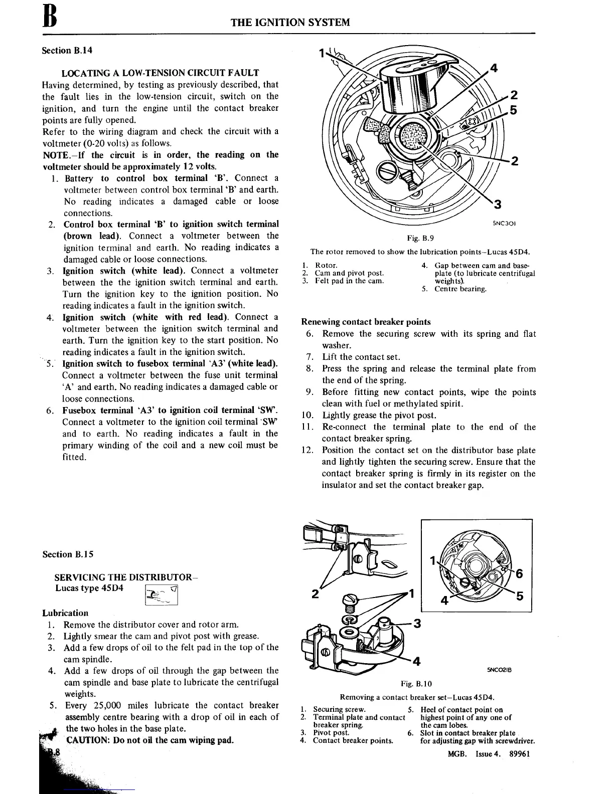
Fig. 3.9
The
rotor
removed
to
show the lubrication
points—Lucas45D4.
l.
2.
3.
Rotor.
4.
Cam
and pivot
post.
Felt pad in the
cam.
Gap between
cam
and base-
plate (to lubricate centrifugal
weights).
_
5. Centre bearing.
Renewing
contact
breaker
points
6.
7.
8.
9.
10.
11.
12.
PE”
59’."
Remove the
securing
screw
with
its spring and
■at
washer.
Lift the
contact set.
Press the
spring and
release the terminal plate
from
the
end
of the
spring.
Before ■tting
new
contact
points, wipe
the
points
clean with fuel
or
methylated
spirit.
Lightly
grease
the
pivot
post.
Re-connect the terminal plate
to
the end of
the
contact
breaker
spring.
Position the
contact set
on
the
distributor
base plate
and lightly tighten the
securing
screw.
Ensure that the
contact
breaker
spring is
■rmly
in its register
on
the
insulator
and
set
the
contact
breaker
gap.
5NCO2IB
Fig.
3.10
Removing
a
contact
breaker
set—Lucas
45D4.
Securing
screw.
5.
Terminal plate
and
contact
breaker
spring.
Pivot
post. 6.
Contact breaker
points.
Heel
of
contact
point
on
highestpoint
of
any one
of
the
cam
lobes.
Slot
in
contact
breakerplate
for adjusting
gap
with screwdriver.
MGB.
Issue4. 89961