A
THE
ENGINE
Unscrew
and
remove
the
two
securing
screws
and
then
remove
the
tensioner
and
its
backplate.
Unlock
and
remove
the
camshaft
chain wheel
nut
and
remove
the
nut
and
lock washer. Note that
the locating
tag
on
the lock
washer
■ts
into
the keyway
of
the
camshaft
chain wheel.
The
camshaft and
crankshaft chain wheels
may now
be
removed,
together
with the
timing
chain, by
easing
each
wheel
forward,
a
fraction
at
a
time,
with suitable smaller
levers.
As
the
crankshaft
gear
wheel
is
withdrawn
care
must
be
taken
not to
lose
the
gear
packing washers
immediately
behind
it.
When reassembling
replace the
same
number
of
washers
as was
found when dismantling,
unless
new
camshaft
or
crankshaft
components
have
been
■tted which
will disturb the
alignments
of the
two
gear
wheels.
To
determine the thickness
of washers required place
a
straight
edge
across
the
sides
of the
camshaft wheel teeth
and
measure
with
a
feeler
gauge the
gap
between
the
straight-edge and the
crankshaft
gear.
Subtract .005
in.
(~13
mm.)
from the feeler
gauge
reading and add
the resultant
thickness of crankshaft
gear
packing washers.
When replacing the
timing
chain and
gears,
set
the
crankshaft with
its
keyway
at
T.D.C., and the
camshaft
with
its
keyway approximately
at
the
one
o’clock
position
when
seen
from the
front.
Assemble
the
gears
into
the
timing
chain with
the
two
marks
on
the
gear
wheels
opposite
to
each other,
as
in
Fig. A.l
1.
Keeping the
gears
in
this
position,
engage
the
crankshaft
gearrkeyway
with the
key
on
the crankshaft and
rotate
the
camshaft
until the
camshaft
gear
keyway and key
are
aligned. Push the
gears
onto
the
shafts
as
far
as
they will
go
and
secure
the
camshaft
gear
with the lock washer and
nut.
Replace
the
oil
thrower, with the face marked
‘F’
or
the
concave
side
(early-type)
away
from the
engine,
and the
remaining
components.
=.
/
Z;
%
A4
866
Fig. A.4
Checkingthe chain wheel alignment with
a
straightedge and
feeler
gauge
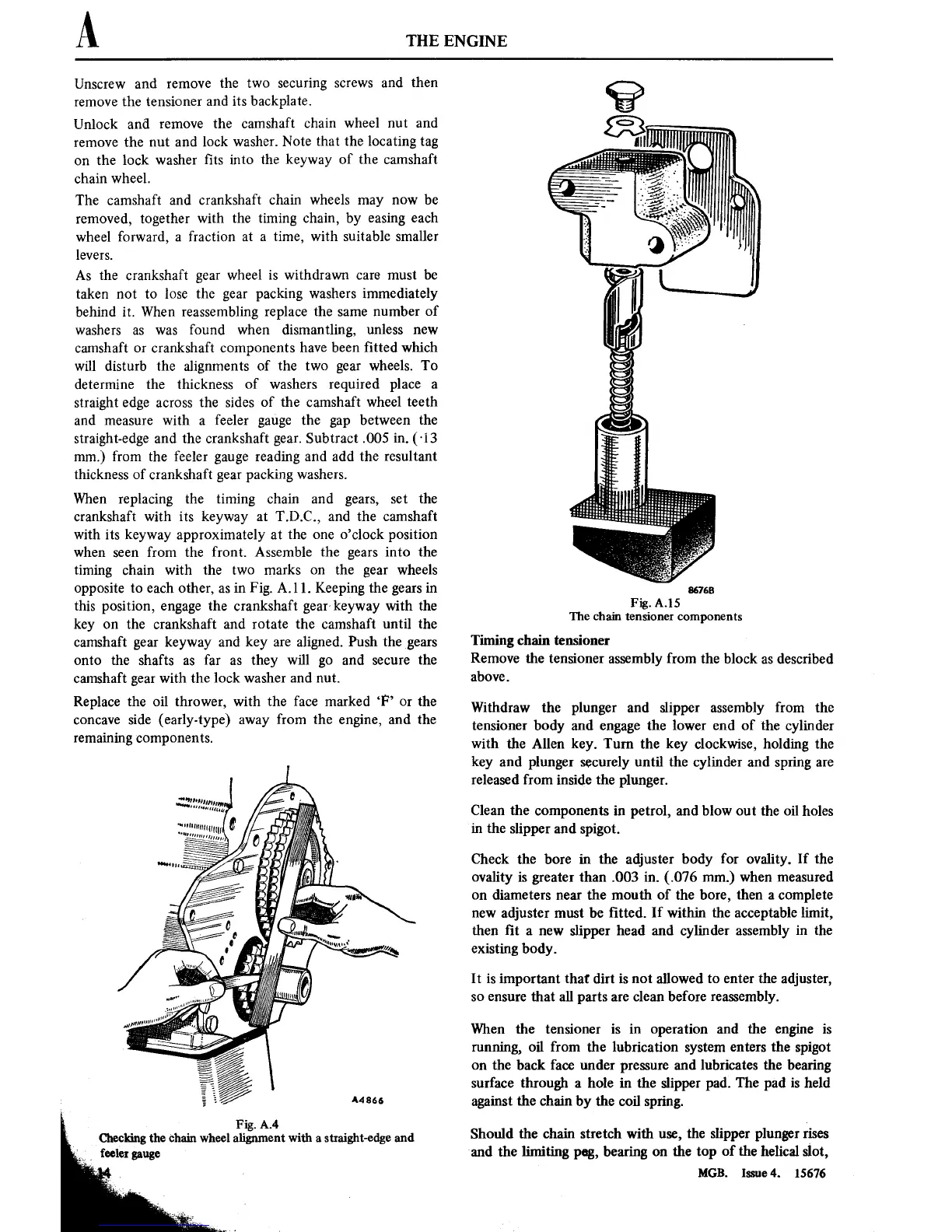
86768
Fig. A.15
The chain
tensioner
components
Timing
chain
tensioner
Remove
the
tensioner
assembly from the
block
as
described
above.
Withdraw the
plunger and slipper assembly
from
the
tensioner
body and
engage
the lower
end
of
the cylinder
with the
Allen key. Turn
the
key clockwise, holding the
key
and plunger securely until
the
cylinder and
spring
are
released from
inside
the
plunger.
Clean the
components
in
petrol, and blow
out
the oil holes
in
the
slipper and
spigot.
Check the bore
in
the adjuster body
for
ovality.
If the
ovality
is
greater
than
.003
in.
(.076 mm.) when measured
on
diameters
near
the mouth of the bore,
then
a
complete
new
adjuster
must
be
■tted.
If
within the acceptable limit,
then ■t
a new
slipper head and cylinder
assembly
in
the
existing
body.
It
is important
that dirt
is
not
allowed
to
enter
the adjuster,
so ensure
that all
parts
are
clean
before reassembly.
When
the
tensioner is in operation
and the
engine is
running,
oil from the lubrication
system enters
the
spigot
on
the back face under
pressure
and lubricates
the
bearing
surface through
a
hole
in
the slipper
pad. The pad
is
held
against
the
chain by the coil
spring.
Should
the chain stretch with
use,
the slipper plunger
rises
and the limiting
peg,
bearing
on
the
top
of the
helical slot,
MGB. lssue4.
15676