THE
BO
DY
R
Unscrew the
four
screws
securing
the hinge
bracket
to
the
body
and
remove
the hinge and bracket
assembly.
Refitting
Re■tting
is
a
reversal
of
the removal
sequence,
but before
finally
tightening
the hinge leaf
screws ensure
that
the
door
lock
engages
correctly
and
that
the door
is correctly
positioned with the
body.
Section R.19
WINDSCREEN
AND BACK-LIGHT GLASSES
(GT)
Removing
Lift the windscreen
wiper
arms
clear
of the
glass.
Remove
the
■nisher strip.
Prise
up
the end
of
the locking filler
and carefully pull
it
from the
channel
in
the surround rubber.
'
Press the glass from
inside
the
car,
commencing
at
a corner,
and
ease
the
surround rubber
from
the metal edge of
the
body
aperture.
Refitting
If
the glass has been broken,
remove
any
pieces
which
remain in
the channel. Examine
the rubber, and
use
a new
rubber should there be
any
signs
of
damage
or
deterioration.
Fit the surround rubber
to
the body
aperture
and
lubricate
the ‘glass’
channel with
a
soap-and-water
solution.
Place
the glass
into
the
lower channel of the
rubber
surround and
commence
at
the
corner
to
lift the lip
of
the
rubber
over
the
glass,
using
Service tool ISO 468. Use
the
short
peg
on
the handle of the installation tool for this
purpose.
Apply
a
soap-and-water solution
to
the
locking
filler
strip
channel
to
assist in
■tting the
strip.
Using Service tool 18G 468
with
adaptor 18G 468
A,
thread
the
end of
the ■ller
strip
through the
eye
of the
adaptor and under the roller.
Lay
the ■ller
strip
in
position
/
Fig. R.
Use
Service tool 18G
468
to
ease
the
channel
lip
over
the
windscreen
or
backlight
glass
MGB.
Issue3.
1329
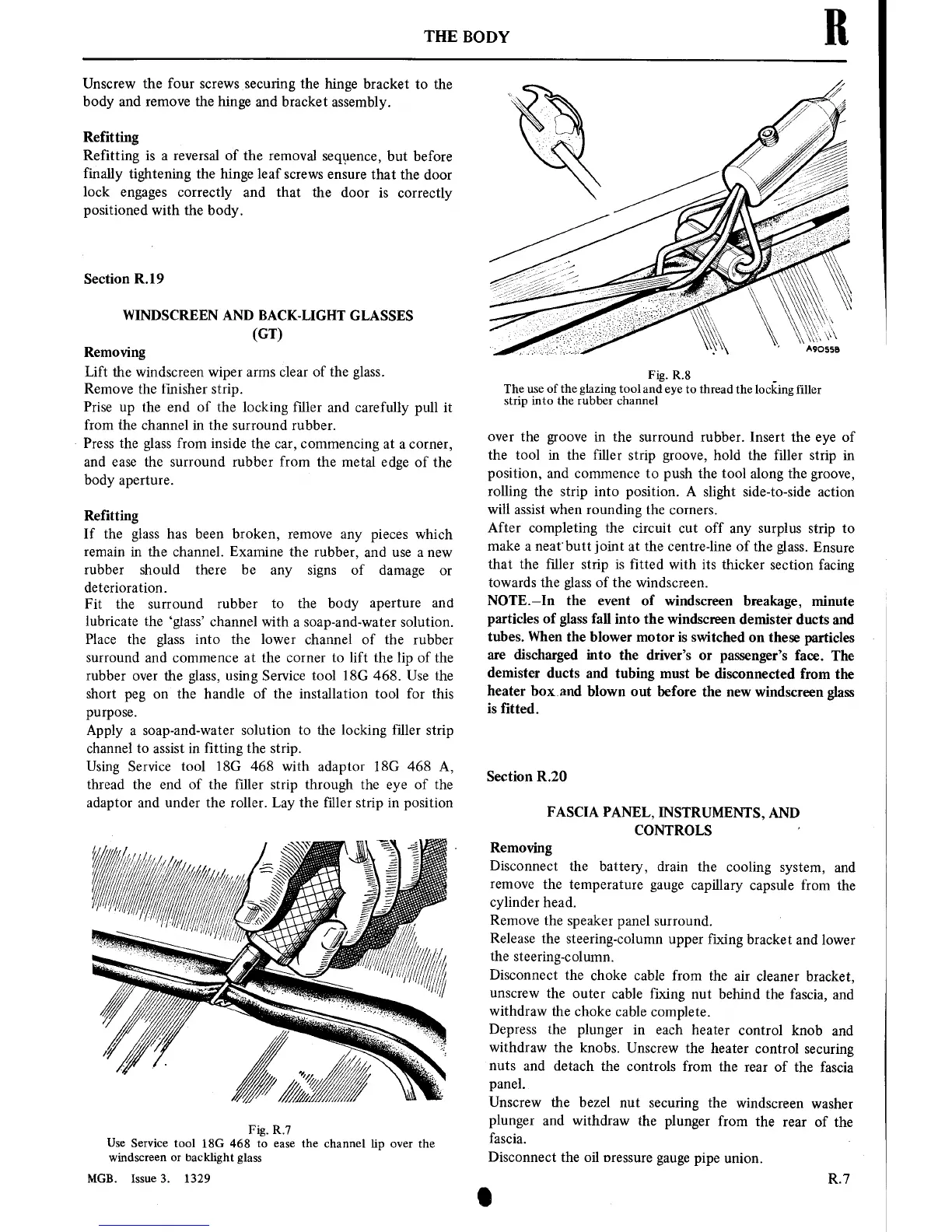
A9OSSB
Fig. R8
The
use
of the glazing
tool and
eye
to
thread
the
locking
■ller
strip into the rubber channel
over
the
groove
in
the
surround rubber.
Insert
the
eye
of
the tool
in
the filler
strip
groove,
hold the filler
strip in
position,
and
commence
to
push the
tool along the
groove,
rolling the
strip into position.
A
slight
side-to-side
action
will
assist
when rounding the
corners.
After completing the
circuit
cut
off
any
surplus
strip
to
make
a
neat'butt
joint
at
the centre-line of the
glass.
Ensure
that the ■ller
strip
is
fitted
with
its
thicker
section
facing
towards the
glass
of
the windscreen.
NOTE—In
the
event
of windscreen
breakage,
minute
particles
of
glass fall
into
the
windscreen demister ducts
and
tubes. When the
blower
motor
is
switched
on
these particles
are
discharged
into
the driver’s
or
passenger’s
face.
The
demister
ducts and
tubing
must
be disconnected
from the
heater
boxand
blown
out
before the
new
windscreen
glass
is
fitted.
Section R.20
FASCIA
PANEL,
INSTRUMENTS,
AND
CONTROLS
’
Removing
Disconnect
the battery,
drain the
cooling
system,
and
remove
the
temperature
gauge
capillary
capsule from the
cylinder head.
Remove the speaker
panel
surround.
Release the
steering-column
upper
fixing
bracket
and lower
the
steering-column.
Disconnect
the choke
cable from the
air
cleaner
bracket,
unscrew
the
outer
cable fixing
nut
behind the fascia,
and
withdraw
the choke
cable
complete.
Depress the plunger
in
each heater
control knob
and
withdraw
the
knobs. Unscrew the heater
control
securing
nuts
and detach
the controls from
the
rear
of
the fascia
panel.
Unscrew the bezel
nut
securing
the
windscreen
washer
plunger
and withdraw
the plunger
from
the
rear
of
the
fascia.
Disconnect the oil
pressure
gauge
pipe
union.
R.7