I]
THE
STEERING GEAR
Section
I
.6
RACK AND
PINION
Dismantling
Hold
the rack
housing between
suitable clamps in
a
vice.
Remove
the
pinion
end
cover
and
joint
washer, placing
a
container
to
catch the oil
that
may
drain from
the housing.
Remove
the damper
cover
and shims,
exposing
the yoke,
damper
pad, and
spring.
After removal
of these the
pinion,
complete with ball
race
and
locknut
may
be
withdrawn.
Unlock the tie-rod
ball end locknuts and disconnect
the ball
end assemblies.
Release the rubber
gaiter
seal clips and
withdraw the seals.
Prise
up
the indentations
in
the
locking
rings
clear of the
slots
in
the rack and
ball housing. Slacken back the locking
ring
and
unscrew
the housing
to
release the tie-rod, ball
seat,
and
seat
tension
spring.
.
Withdraw the rack from the
pinion
end of the housing;
if
removed from the other end
the teeth
may
damage
the rack
housing bush.
To
remove
the rack housing bush
unscrew
the
self—tapping
screw
retaining it
and
carefully
drive
the
bush
out.
A5508W
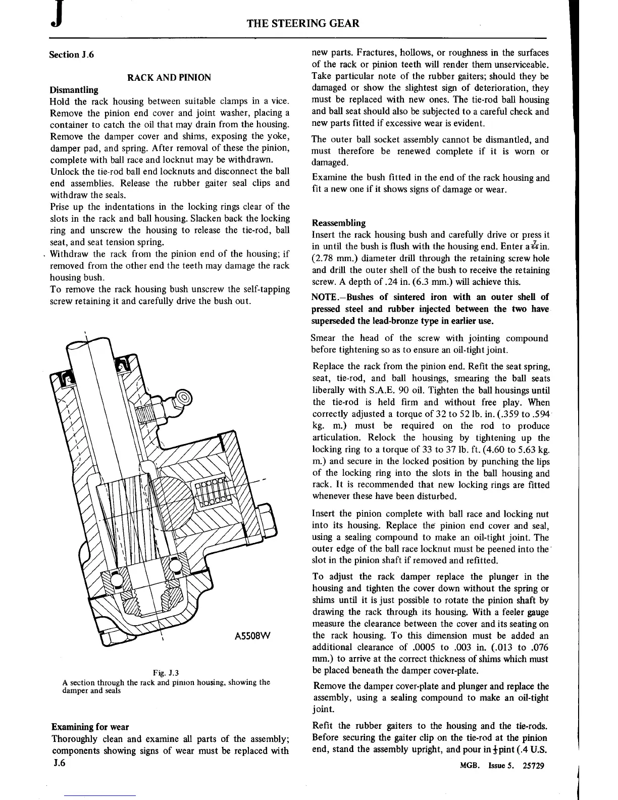
Fig. J.3
A
section through the
rack
and
pinion
housing, showing the
damper
and seals
Examining
for
wear
Thoroughly
clean and
examine
all
parts
of the
assembly;
components
showing
signs
of
wear
must
be replaced with
1.6
new
parts.
Fractures, hollows,
or
roughness
in
the surfaces
of the
rack
or
pinion
teeth will render them
unserviceable.
Take
particular
note
of the
rubber
gaiters;
should they
be
damaged
or
show the slightest
sign
of
deterioration, they
must
be replaced with
new ones.
The tie-rod ball housing
and
ball
seat
should
also be subjected
to
a
careful
check and
new
parts
■tted if
excessive
wear
is
evident.
The
outer
ball socket assembly
cannot
be dismantled, and
must
therefore
be renewed
complete if
it is
worn or
damaged.
Examine the
bush ■tted
in
the end of the
rack housing
and
■t
a new one
if
it
shows
signs
of
damage
or wear.
Reassembling
Insert
the
rack housing
bush
and
carefully
drive
or press
it
in
until the bush
is
flush with the housing end. Enter
again.
(2.78
mm.)
diameter drill through the
retaining
screw
hole
and drill the
outer
shell of the bush
to
receive
the
retaining
screw.
A
depth of
.24 in.
(6.3
mm.)
will achieve this.
NOTE—Bushes of
sintered
iron
with
an
outer
shell of
pressed steel and rubber injected between the
two
have,
superseded the lead-bronze
type
in
earlier
use.
Smear
the head
of the
screw
with
jointing compound
before
tightening
so as
to
ensure an
oil-tight
joint.
Replace the
rack
from the
pinion
end. Re■t the
seat
spring,
seat,
tie-rod, and ball housings,
smearing
the ball
seats
liberally
with S.A.E.
90
oil. Tighten
the ball housings
until
the tie-rod
is
held ■rm
and without free play.
When
correctly adjusted
a
torque
of
32
to
52
lb.
in.
(.359
to
.594'
kg.
m.)
must
be
required
on
the rod
to
produce
articulation.
Relock the housing
by tightening
up
the
locking
ring
to
a
torque
of
33
to
37
lb. ft.
(4.60
to
5.63 kg.
m.)
and
secure
in
the
locked
position
by
punching
the
lips
of the
locking
ring into
the slots
in
the
ball housing
and
rack.
It
is recommended
that
new
locking
rings
are
■tted
whenever
these have
been disturbed.
Insert
the
pinion
complete
with ball
race
and locking
nut
into its
housing.
Replace the‘
pinion
end
cover
and seal,
using
a
sealing compound
to
make
an
oil-tight
joint.
The
outer
edge of the ball
race
locknut
must
be peened
into
the’
slot
in
the
pinion
shaft if
removed and re■tted.
To
adjust the
rack damper replace the plunger
in
the
housing
and tighten the
cover
down without the
spring
or
shims
until
it is just
possible
to
rotate
the
pinion
shaft by
drawing the
rack through
its
housing.
With
a
feeler
gauge
measure
the clearance
between the
cover
and
its seating
on
the
rack housing.
To
this
dimension
must
be added
an
additional clearance
of
.0005
to
.003
in.
(.013
to
.076
mm.)
to
arrive
at
the
correct
thickness of shims which
must
be
placed beneath the
damper cover-plate.
Remove the
damper cover-plate and plunger and replace
the
assembly,
using
a
sealing
compound
to
make
an
oil-tight
joint.
Re■t
the rubber
gaiters
to
the housing and the
tie-rods.
Before
securing
the
gaiter
clip
on
the tie-rod
at
the
pinion
end, stand
the
assembly
upright, and
pour
in
i-pint
(.4
U.S.
MGB.
Issue5. 25729