EasyManuals Logo

MG MGB User Manual

MG MGB
417 pages
To Next Page IconTo Next Page
To Previous Page IconTo Previous Page
Page #377 background imageLoading...
Page #377 background image
I“
THE
BODY
Retting
GRILLE
PANEL
6.
Position the grille panels
on
the finisher,
ensuring
that
the grille panel thin slats
are
in
a vee
formation
when
viewed from
the
front
of
the grille
(see illustration
on
page
C.4).
7.
Fit the
12
screws
and clips
to
secure
the grille
panels
to
the grille finisher.
8. Reverse
the
removing
procedure
in 1
to
3.
GRILLE ASSEMBLY
9.
Reverse the
removing
procedure
in
1
to
3.
Section
R.37
FRONT
BUMPER
ASSEMBLY
Removing
1. Disconnect the battery.
2. Disconnect the parking asher
lamp
wiring
at
the
connectors
under the bonnet
and pull
the leads
through
the rubber
grommet
so
they hang
under
the
front
wings.
3.
Remove
the four
nuts
and
eight washers
securing
the
bumper
inner mountings
to
the longitudinal
chassis
members.
4.
Remove the four bolts
and eight
washers
securing
the
bumper
to
the
outer
springs.
5.
Remove the bumper
assembly
and collect
the
two
towing
eyes
from
the
outer
springs,
and the
spacer
plates
(if
tted)
from
the
inner
mountings,
noting
the
quantity
of
spacer
plates
on
each
side.
Dismantling
6.
Remove the
two
bolts
and washers
to
release
the
number-plate
assembly.
7. Remove the lamp
lens
and lamp assemblies.
Remove the
‘MG’
motif.
9. Drill
the heads
of the four
rivets and
remove
the
support
tube.
[0. Drill the
heads off the
rivets
securing the rubber
bumper bar
to
the
armature,
levering
the rubber
clear
of the
top
rivets
as
necessary.
ll. Punch the
rivets
through
into
the
armature
and
remove
the clamping
plates.
.2.
Remove the
armature
from the
rubber.
00
(eassembling
3. Ensure
that the
new
rivets
t all
the holes
in
the
rubber;
if
necessary
clear
the
holes
with
a
drill.
4. Fit the
armature
into the rubber,
ensuring
that
the
number-plate
bracket holes
are
towards
the
bottom
of
the
assembly.
.5. Fit the
bottom clamping
plate
and
insert
the
centre
rivet and
both
end
rivets.
.6.
Secure the
three tted
rivets.
[7.
Fit and
secure
the
remainder of
the
bottom
rivets.
R.28
5
5NC
372
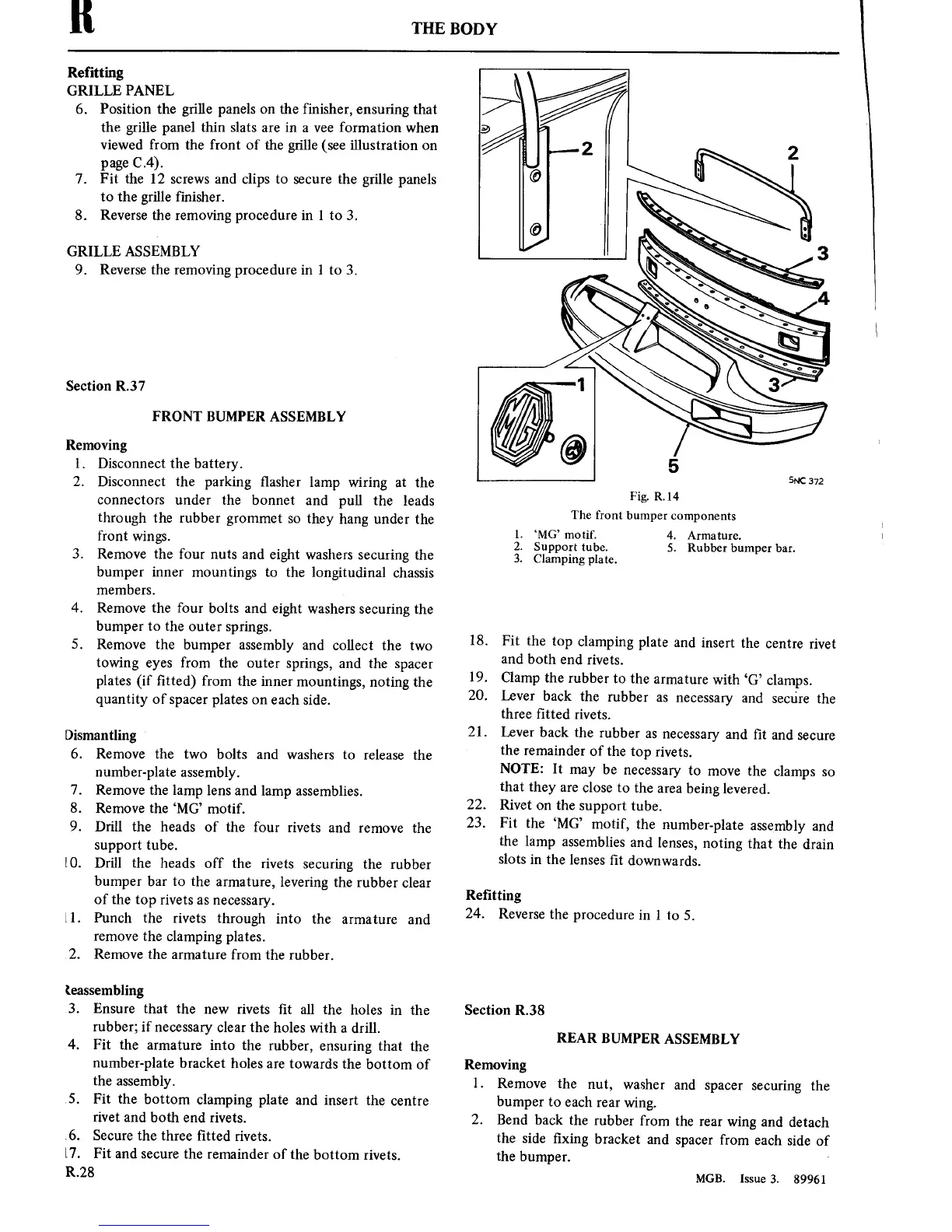
Fig.
RM
The front
bumper
components
1. ‘MG’
motif.
2.
Support
tube,
3.
Clamping
plate.
4.
Armature.
5.
Rubber
bumper
bar.
18.
Fit the
top
clamping
plate
and
insert the
centre
rivet
and both
end
rivets.
19.
Clamp
the
rubber
to
the
armature
with ‘G’
clamps.
20.
Lever back
the
rubber
as
necessary
and
secure
the
three
tted
rivets.
21.
Lever back
the
rubber
as
necessary
and t
and
secure
the
remainder of
the
top
rivets.
NOTE:
It
may
be
necessary
to
move
the
clamps
so
that
they
are
close
to
the
area
being
levered.
22.
Rivet
on
the
support
tube.
23.
Fit
the
‘MG’
motif,
the
number-plate
assembly
and
the lamp
assemblies
and lenses,
noting that
the
drain
slots
in
the lenses
t
downwards.
Retting
24.
Reverse
the
procedure
in l
to
5.
Section
R.38
REAR
BUMPER
ASSEMBLY
Removing
1.
Remove
the
nut,
washer
and
spacer
securing
the
bumper
to
each
rear
wing.
2.
Bend back
the rubber
from
the
rear
wing
and detach
the
side xing
bracket
and
spacer
from
each
side of
the bumper.
'
MGB.
Issue
3. 89961

Table of Contents

Questions and Answers:

Question and Answer IconNeed help?

Do you have a question about the MG MGB and is the answer not in the manual?

MG MGB Specifications

General IconGeneral
BrandMG
ModelMGB
CategoryAutomobile
LanguageEnglish

Related product manuals