M
THE BRAKING SYSTEM
Dismantling
the calliper
Further servicing
of the calliper
should be
con■ned
to
removing
the
bleeder
screw
and the
■uid
pipe
line
and
blowing
the
■uid
passages
clear with
compressed
air.
Unless
it
is
absolutely
unavoidable the calliper
should
not
be
separated
into
two
halves.
In
the
event
of
separation
becoming
essential, the ■uid
channel seal, clamping
bolts,
and lock
plates
must
be
renewed when
reassembling. Only
bolts
supplied by BMC Service
Ltd.
may
be
used.
0n
assembly these
must
be
tightened
with
a
torque
wrench
set
at
between 35.5
and 37
lb. ft. (4.9 and 5.1 kg.
m.).
Ensure
that
the calliper
faces
are
clean and that
the
threaded bolt holes
are
thoroughly dry. Make
certain
that
the
new
■uid channel
seal
is
correctly located
in
the
recessed face
before assembling
the
two
calliper halves.
Section M.7
BRAKE DISCS
Removing
Remove
the brake
calliper
as
detailed
in
Section M.6
without disconnecting
the
■uid supply and
withdraw the
hub by the
method described
in
Section
K.
Separate
the disc
from the hub
by
removing
the four
securing
nuts
and
washers.
Replacing
Assemble the brake
disc
to
the hub
and re■t the assembly
to
the swivel
hub.
Check
the disc
for
true
rotation
by clamping
a
dial
indicator
to
a
suitable fixed
point
on
the
vehicle with the
needle pad
bearing
on
the
face of the hub.
Run-out
must
not
exceed
.003
in.
(.076
mm.)
and
in
the
event
of this
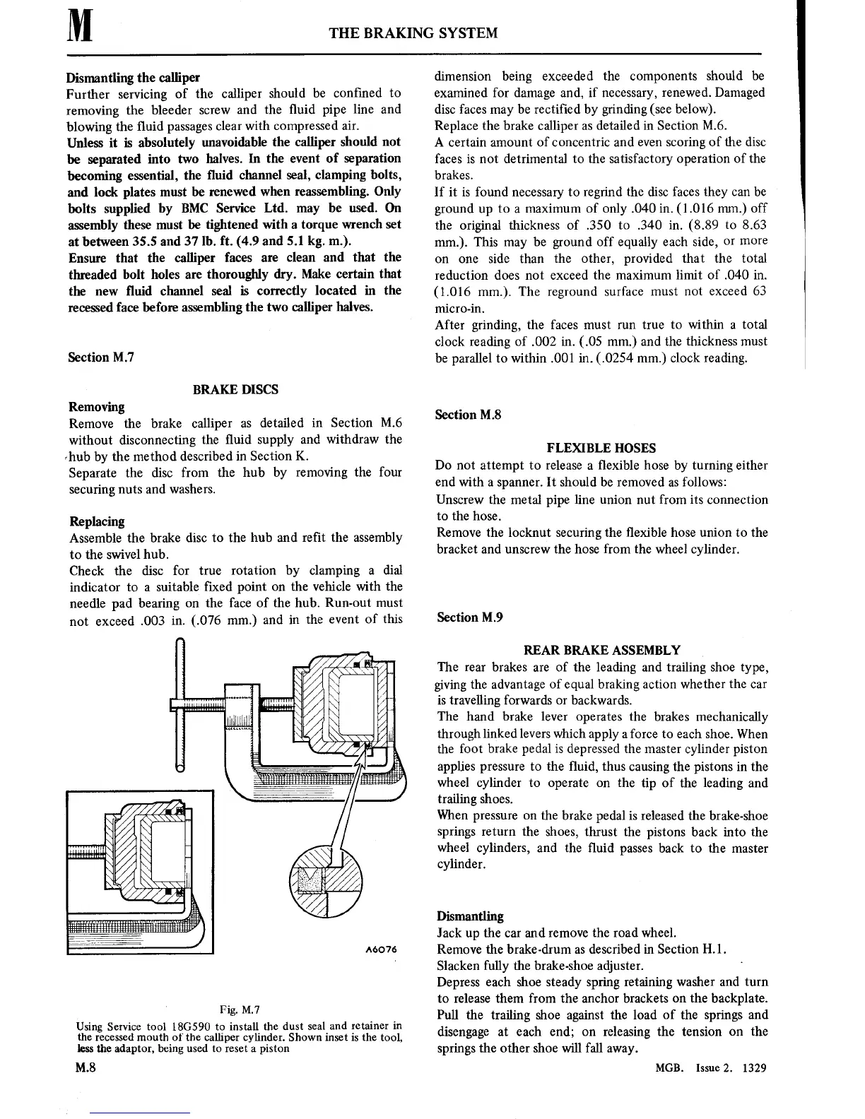
A6076
Fig.
M.7
Using
Service tool
18G590
to
install the
dust
seal
and retainer in
the recessedmouth
of
the calliper cylinder.
Shown inset is the
tool,
lessthe adaptor, being
used
to reset
a
piston
M.8
dimension being exceeded the
components
should be
examined
for
damage and,
if
necessary,
renewed. Damaged
disc faces
may
be
rectified by grinding
(see below).
Replace
the brake calliper
as
detailed
in
Section M.6.
A
certain
amount
of
concentric
and
even
scoring
of the
disc
faces
is
not
detrimental
to
the satisfactory
operation
of
the
brakes.
If
it is
found
necessary
to
regrind the disc faces they
can
be
ground
up
to
a
maximum
of
only .040
in.
(1.016 mm.) off
the original thickness
of
.350
to
.340
in.
(8.89
to
8.63
mm.).
This
may
be ground off equally each side,
or
more
on one
side than the other, provided
that the total
reduction
does
not
exceed the
maximum
limit
of
.040
in.
(1.016
mm.).
The
reground surface
must not
exceed
63
micro-in.
After grinding, the faces
must
run
true
to
within
a
total
clock reading of .002
in.
(.05 mm.)
and the thickness
must
be
parallel
to
within
.001
in.
(.0254 mm.)
clock reading.
Section M.8
FLEXIBLE HOSES
Do
not attempt to
release
a
■exible hose
by
turning
either
end with
a spanner.
It
should be removed
as
follows:
Unscrew the metal
pipe
line
union
nut
from
its connection
to
the
hose.
Remove the locknut
securing
the
■exible hose
union
to
the
bracket
and
unscrew
the
hose from the wheel
cylinder.
Section M.9
REAR BRAKE ASSEMBLY
The
rear
brakes
are
of
the leading and trailing shoe
type,
giving
the advantage
of
equal braking
action
whether the
car
is
travelling forwards
or
backwards.
The hand brake
lever
operates
the brakes mechanically
through
linked levers which
apply
a
force
to
each shoe.
When
the
foot
brake pedal
is
depressed the
master
cylinder
piston
applies
pressure
to
the ■uid, thus
causing
the
pistons in
the
wheel
cylinder
to operate
on
the
tip
of the
leading and
trailing
shoes.
When
pressure on
the brake
pedal
is
released the brake-shoe
springs
return
the shoes, thrust
the
pistons
back
into
the
wheel
cylinders, and the ■uid
passes
back
to
the
master
cylinder.
Dismantling
Jack
up
the
car
and
remove
the
road wheel.
Remove
the brake-drum
as
described
in
Section
H.l.
Slacken
fully the brake-shoe adjuster.
Depress
each shoe steady
spring retaining
washer and
turn
to
release
them from the anchor brackets
on
the
backplate.
Pull the
trailing
shoe
against
the load of the
springs
and
disengage
at
each
end;
on
releasing the
tension
on
the
springs
the other shoe
will
fall
away.
MGB.
Issue2. 1329