I
THE
GEARBOX (ALL SYNCHROMESH)
((((((((((O
\\\\\\\\
\\
\\\\\\\\
7
2.,\\\\\\\\\\
«((099
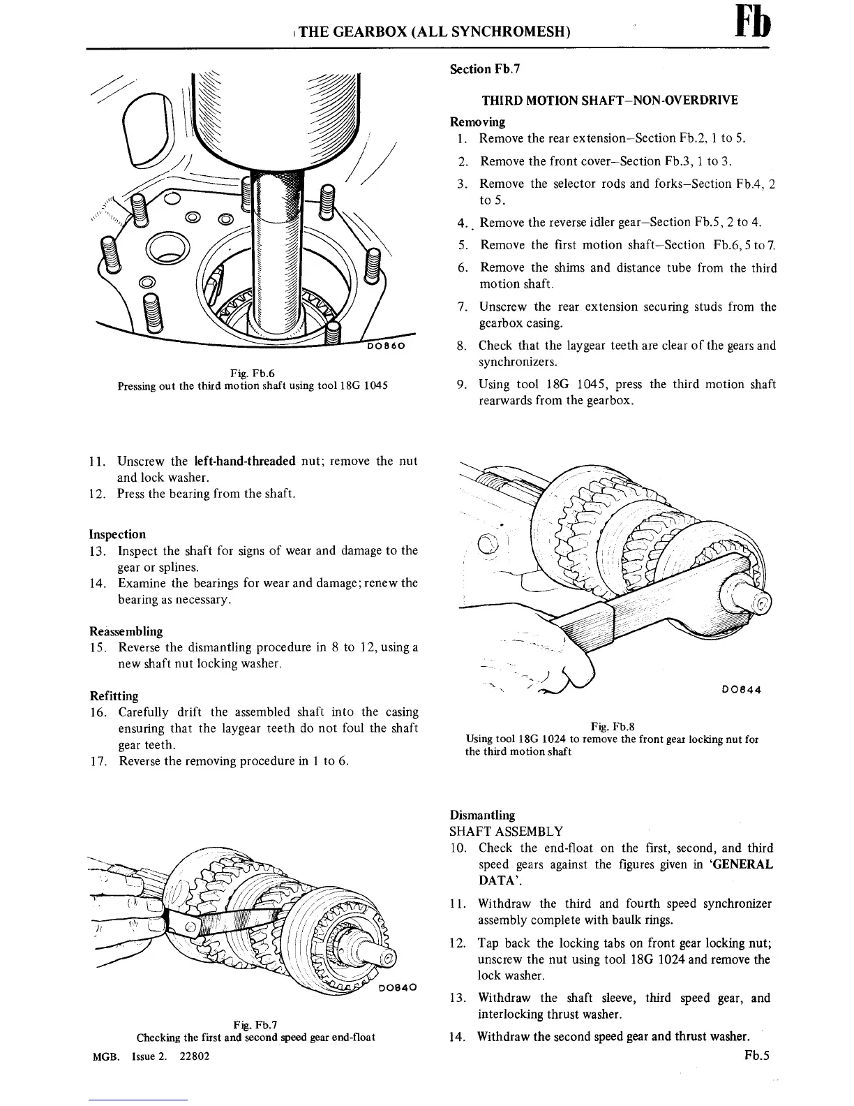
Fig. Fb.6
Pressing
out
the
third motion
shaft
using
tool 18G 1045
11.
Unscrew the
left-hand-threaded
nut;
remove
the
nut
and
lock washer.
12.
Press the
bearing
from the shaft.
Inspection
13.
Inspect
the
shaft for
signs
of
wear
and damage
to
the
gear or
splines.
14.
Examine
the
bearings
for
wear
and damage;
renew
the
bearing
as
necessary.
Reassembling
15. Reverse
the dismantling
procedure
in
8
to
12, using
a
new
shaft
nut
locking washer.
Refitting
16.
Carefully
drift the assembled shaft
into
the
casing
ensuring
that the laygear teeth do
not
foul the shaft
gear
teeth.
17.
Reverse
the
removing
procedure
in 1
to
6.
Fig. Fb.7
Checking the
first and
secondspeed
gear
end-float
MGB. Issue
2.
22802
Fl)
Section
Fb.7
THIRD
MOTION
SHAFT—NON-OVERDRIVE
Removing
1.
Remove
the
rear
extensionWSection
Fb.2,
l
to
5.
2.
Remove
the
front
coveriSection
Fb.3,
1
to
3.
3.
Remove
the selector
rods and
forks—Section
Fb.4,
2
to
5.
4.
_
Remove
the
reverse
idler gear—Section
Fb.5,
2
to
4.
Remove
the ■rst
motion
shaftiSection
F b.6,
5
to
7.
6.
Remove the shims
and distance
tube
from
the
third
motion
shaft.
7.
Unscrew the
rear
extension
securing
studs
from
the
gearbox
casing.
8.
Check that the laygear
teeth
are
clear
of the
gears
and
synchronizers.
9.
Using tool
ISO
1045,
press
the
third
motion
shaft
rearwards
from the
gearbox.
Fig. Fb.8
Using tool 18G
1024
to
remove
the front
gear
locking
nut
for
the third motion shaft
Dismantling
SHAFT
ASSEMBLY
10.
Check the end-■oat
on
the ■rst, second, and third
speed
gears
against
the ■gures
given in
‘GENERAL
DATA’.
11.
Withdraw
the
third and
fourth speed synchronizer
assembly complete
with
baulk
rings.
12.
Tap back the
locking
tabs
on
front
gear
locking
nut;
unscrew
the
nut
using
tool 180
1024 and
remove
the
lock washer.
13.
Withdraw the shaft sleeve, third speed
gear,
and
interlocking thrust washer.
14.
Withdraw the second speed
gear
and thrust washer.
Fb.5